


Pulse amplitude modulation (PAM) carries information in the amplitude of a regular train of pulses. Analog PAM takes samples of a message, and digital M-PAM maps groups of bits to one of M levels. PAM is the foundation of sampled systems: DACs produce it, ASK is PAM on a carrier, and QAM is two PAM signals in quadrature.
Unlike amplitude modulation, which varies a continuous carrier, PAM exists only at discrete sample times. This article covers the theory first, then the practical issues of level spacing, pulse shaping and implementation.
What Is Pulse Amplitude Modulation?
A PAM signal is a sequence of symbol amplitudes ak applied to a pulse shape p(t), at symbol rate Rs = 1/T:
s(t) = Σ ak p(t − kT)
Different choices of ak and p(t) give the two main forms.
- Analog PAM: ak are samples of a message. If the message is limited to W hertz, the sampling theorem requires fs ≥ 2W.
- Digital PAM: ak come from a set of levels, usually ±1, ±3, …, ±(M − 1).
PAM differs from pulse code modulation, which turns each sample into a binary number, and from pulse width and pulse position modulation, which vary timing and not height.
Natural and Flat-Top Sampling in PAM
Natural sampling multiplies the message by a pulse train, so pulse tops follow the message. Flat-top sampling holds each sample constant for the pulse width τ, which is what a sample-and-hold or DAC produces.
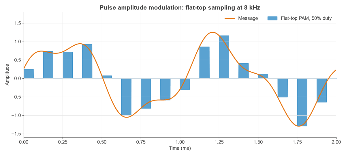
Flat-top pulses filter the spectrum with a sinc shape, the aperture effect:
|H(f)| = sinc(fτ)
For a full-period hold, τ = T, as in a zero-order-hold DAC, the droop is 3.92 dB at fs/2. At 10% duty, the droop is only 0.04 dB. The worked example below applies this to an RF transmitter.
M-ary PAM Levels and PAM-4
M-PAM carries log2M bits per symbol. With Gray coding, adjacent levels differ by a single bit, so a one-level error gives one bit error. PAM-2 is the same as NRZ signalling. PAM-4 uses four levels, carrying two bits per symbol.
For the same peak swing, the levels of PAM-4 sit a third as far apart as NRZ, a penalty of 20 log(1/3) = −9.5 dB in vertical eye opening. In exchange, the symbol rate falls by half for the same bit rate. This trade is good on channels whose loss rises quickly with frequency.
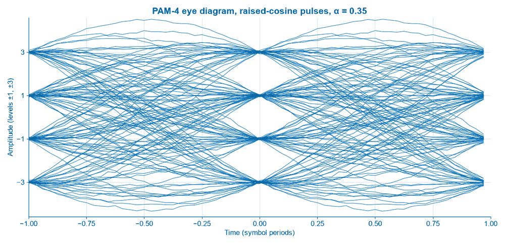
High-speed serial links are the best-known use today. Modern 100G-per-lane Ethernet electrical and optical interfaces typically use PAM-4 at about 53.125 GBd, for 106.25 Gbit/s including FEC overhead. The Nyquist frequency is 26.56 GHz, half of the 53.1 GHz that NRZ would need at the same bit rate.
Pulse Shaping and Bandwidth
Rectangular pulses have wide sinc spectra, and they do not suit a band-limited channel. Pulses are therefore shaped so that the spectrum is limited while the waveform is still zero at other sampling instants, which is the Nyquist criterion for no intersymbol interference. The raised-cosine family achieves this with a roll-off α:
B = (1 + α) Rs / 2 at baseband, or (1 + α) Rs on a carrier.
Filtering is usually split between transmitter and receiver as a root-raised-cosine pair, which forms a matched filter for the best SNR.
PAM Bit Error Rate in AWGN
With Gray coding, a matched filter and equally likely levels, the bit error rate is well approximated by:
Pb ≈ (2/log2M)(1 − 1/M) Q(√(6 log2M/(M² − 1) × Eb/N0))
| Format | Bits per symbol | Eb/N0 at BER 10−6 |
|---|---|---|
| 2-PAM | 1 | 10.5 dB |
| 4-PAM | 2 | 14.4 dB |
| 8-PAM | 3 | 18.8 dB |
| 16-PAM | 4 | 23.5 dB |
Each extra bit per symbol costs a growing amount of Eb/N0, about 4 to 5 dB here. A Monte Carlo run of 4-PAM at 12 dB gave a symbol error rate of 2.76 × 10⁻⁴ against the formula’s 2.77 × 10⁻⁴.
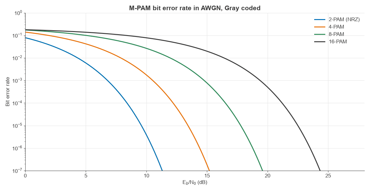
Note that PAM uses only one real dimension. QAM adds a second dimension at the same bandwidth, so 16-QAM needs the same Eb/N0 as 4-PAM for twice the bits per symbol on a carrier. That is why radio links favour QAM and why pure PAM stays common on baseband wires and fibre.
PAM in RF Systems
PAM appears throughout RF design, usually inside other formats.
- ASK is PAM on a carrier, and the BER of 2-level bipolar PAM on a carrier equals that of BPSK.
- QAM is built from two PAM rails. A 64-QAM transmitter drives I and Q with 8-PAM each.
- OFDM subcarriers are QAM symbols, so PAM is present at each one.
- Every DAC output is a flat-top PAM of its input samples.
- Radar and pulsed systems shape the pulse amplitude to control sidelobes.
Worked Example: DAC Droop in an I/Q Transmitter
A transmitter sends QAM at 20 Msym/s with α = 0.35 through a pair of DACs at 100 MS/s, which act as flat-top PAM.
- Occupied RF bandwidth: (1 + 0.35) × 20 = 27 MHz, or ±13.5 MHz about the carrier.
- Zero-order-hold droop at 30 MHz, if the signal is centred there digitally: −20 log(sinc(30/100)) = 1.33 dB, rising from 0.39 dB at the 16.5 MHz band edge to 2.90 dB at 43.5 MHz.
- Droop at fs/2 = 50 MHz: 3.92 dB.
The 2.5 dB tilt across the band is far from negligible for a high-order signal, so it is typically corrected with an inverse-sinc digital filter. Images around multiples of 100 MHz are also present, since a stepped PAM waveform has them, and a reconstruction filter removes them. See I/Q modulators and demodulators for the following stage, and EVM and PAPR for the effect of such errors.
Implementing a PAM Transmitter and Receiver
A transmitter normally has the following blocks.
- Bit mapper, with Gray coding.
- Pulse-shaping filter, usually digital and oversampled.
- DAC and reconstruction filter.
- Optional upconverter to RF, followed by a linear power amplifier.
The receiver reverses this chain.
- Matched filter or analog front end with equalization.
- Timing recovery, which selects the point of maximum eye opening.
- Slicer, with decision levels placed midway between symbol levels.
- Gain control, because multilevel slicers need an accurate amplitude reference.
Level linearity matters as well. If the middle eye of PAM-4 is smaller than the outer ones through compression, that eye alone sets the BER. Peak-to-average ratio also rises with M, which pushes amplifier back-off higher.
Frequently asked questions
What is pulse amplitude modulation used for?
It is used in sampling and DACs, wired and optical high-speed links as PAM-4, and as the building block of ASK and QAM. Early telephone multiplexing also used analog PAM.
What is the difference between PAM and QAM?
PAM uses amplitude in one dimension. QAM runs two PAM signals on quadrature carriers, which doubles the bits per symbol in the same RF bandwidth at the same Eb/N0.
What is PAM-4?
It is a four-level PAM that carries two bits per symbol, halving the symbol rate compared with NRZ. Its eye openings are a third as tall for the same swing.
What is the difference between PAM and PCM?
PAM keeps each sample as an analog height or a multilevel symbol. PCM quantizes the sample and transmits it as binary digits.
Related topics
See amplitude shift keying and frequency shift keying for keyed carriers, amplitude modulation and demodulation and frequency modulation for analog methods, and continuous wave modulation for background. The digital modulation comparison and the RF fundamentals hub go further.