


Phase modulation (PM) is an analog angle modulation method in which the instantaneous phase of a carrier changes in proportion to the message signal, while the amplitude stays constant. It is closely related to frequency modulation: PM of a signal is the same as FM of that signal’s derivative. Its discrete form, phase shift keying, underlies most digital radio.
This introduction covers the signal mathematics, the spectrum, the link to FM, and why the same equations also describe phase noise in oscillators.
The Phase Modulation Equation
A phase-modulated carrier with message m(t) is:
s(t) = A cos(2πfct + kpm(t))
Here kp is the phase sensitivity in radians per volt. All the information sits in the angle, and the envelope A is constant. That makes the signal tolerant of amplifier compression, and a saturated amplifier can be used without creating AM-PM problems of the kind that afflict amplitude-bearing signals.
Phase and Frequency: Instantaneous Frequency
Frequency is the rate of change of phase. Differentiating the total angle and dividing by 2π gives the instantaneous frequency:
fi(t) = fc + (kp/2π) dm/dt
So in PM, the frequency deviation follows the slope of the message, not its value. For a sinusoidal message m(t) = Am sin(2πfmt), the peak phase deviation is the modulation index β = kpAm in radians, and the peak frequency deviation is Δf = βfm.
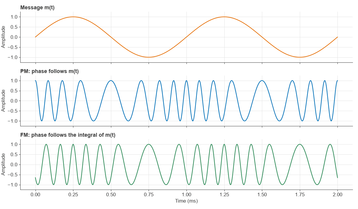
Phase Modulation Versus Frequency Modulation
The two methods form a pair:
| Property | Phase modulation | Frequency modulation |
|---|---|---|
| Quantity proportional to m(t) | Phase | Instantaneous frequency |
| Phase term | kpm(t) | 2πkf∫m(t)dt |
| Modulation index for a tone | β = kpAm, independent of fm | β = Δf/fm, falls as fm rises |
| Peak deviation for a tone | Δf = βfm, rises with fm | Δf = kfAm, independent of fm |
| Amplitude | Constant | Constant |
A single tone cannot tell them apart. The difference only shows as the modulating frequency changes. Feeding the integral of a message into a phase modulator produces FM, a method known as indirect FM and long used in land mobile radios. Feeding the derivative of a message into a frequency modulator produces PM.
The two also differ in demodulated noise. A phase detector gives a flat output noise spectrum, whereas an FM discriminator’s output noise rises with baseband frequency. This is why FM systems apply pre-emphasis.
Spectrum, Bessel Functions and Bandwidth
For a sinusoidal message, the signal expands into a carrier and infinite sidebands spaced at fm:
s(t) = A Σ Jn(β) cos(2π(fc + nfm)t)
Jn(β) is the Bessel function of the first kind and order n. Total power is unchanged by modulation, since the squares of all Jn(β) sum to 1. Modulation only moves power from the carrier into sidebands.
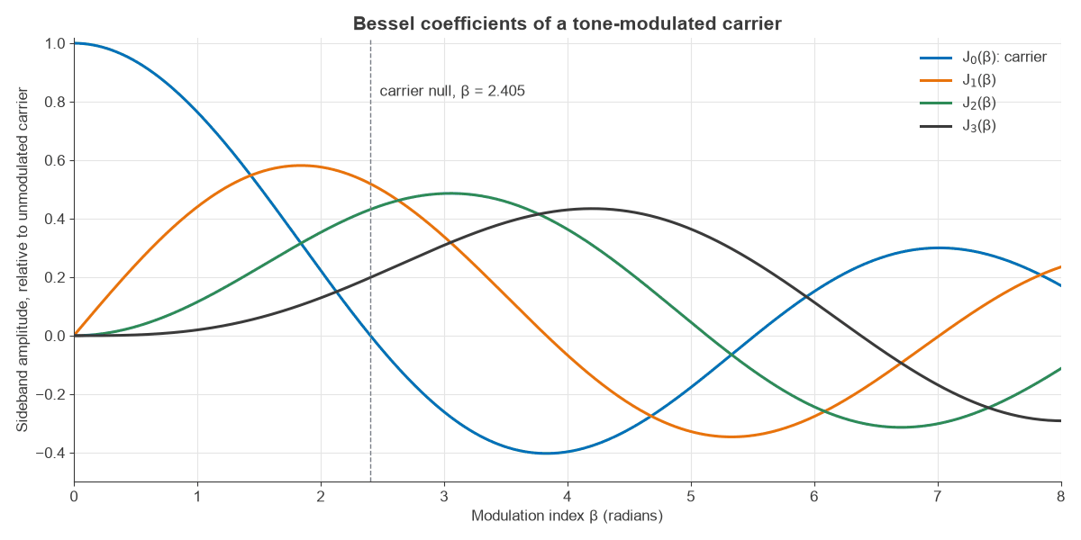
The carrier term J0(β) reaches zero at β = 2.405. That null, plotted in Figures 2 and 3, gives a convenient way to calibrate a modulator: raise the drive while watching a spectrum analyzer until the carrier disappears.
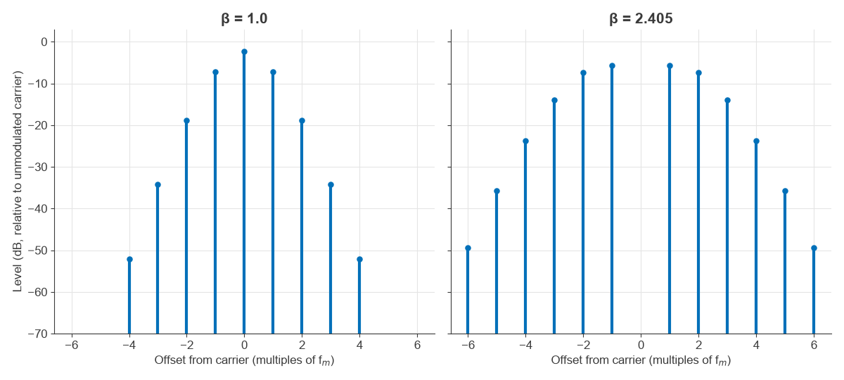
Carson’s rule estimates the occupied bandwidth as B ≈ 2(β + 1)fm = 2(Δf + fm).
Narrowband phase modulation
When β is small, J0 ≈ 1 and J1 ≈ β/2, and only the first sidebands matter. The signal then resembles AM with the carrier rotated by 90 degrees, and each sideband sits at 20log10(β/2) dBc.
Worked Example: A Tone-Modulated PM Transmitter
A modulator with kp = 2 rad/V is driven by a 0.5 V peak tone at fm = 5 kHz.
- Modulation index: β = 2 × 0.5 = 1.0 rad.
- Peak frequency deviation: Δf = 1.0 × 5 kHz = 5 kHz.
- Carson bandwidth: 2(5 + 5) = 20 kHz.
The Bessel coefficients give the levels relative to the unmodulated carrier:
| Component | Jn(1.0) | Level (dB) |
|---|---|---|
| Carrier, n = 0 | 0.7652 | −2.32 |
| First sidebands, n = 1 | 0.4401 | −7.13 |
| Second sidebands, n = 2 | 0.1149 | −18.79 |
| Third sidebands, n = 3 | 0.0196 | −34.17 |
The carrier and two pairs of sidebands contain J02 + 2J12 + 2J22 = 0.9992 of the power, so Carson’s 20 kHz captures 99.92%. Doubling the tone to 10 kHz at the same drive keeps β at 1.0 but doubles the deviation to 10 kHz and the bandwidth to 40 kHz. An FM transmitter with the same 5 kHz deviation would stay at 5 kHz, and its bandwidth would rise only to 30 kHz.
Phase Modulation in Practice: Phase Noise and EVM
The same mathematics applies when the “message” is an unwanted disturbance. A spurious tone that phase-modulates an oscillator by β = 0.01 rad creates sidebands at 20log10(0.005) = −46.02 dBc, and the exact Bessel ratio gives the same value. Noise on a voltage-controlled oscillator’s tuning line does this continuously, which is the origin of the skirts around a carrier described under phase noise.
Random phase error also has a direct digital cost. A constellation point with phase error φ lands in error by |ejφ − 1|, and for Gaussian φ of RMS value σ, in radians, the RMS error vector is √(2 − 2e−σ²/2), which is close to σ for small angles.
| RMS phase error (degrees) | EVM (%) |
|---|---|
| 0.5 | 0.87 |
| 1 | 1.75 |
| 2 | 3.49 |
| 5 | 8.72 |
A two million sample simulation at 2 degrees gave 3.49%, matching the formula. A 2 degree phase error alone would use up the whole of a typical 256-QAM limit of about 3.5%, and this is why PLL frequency synthesis receives so much design attention.
Generating and Demodulating PM
- Direct phase modulators vary a reactance in a tuned circuit, or use a varactor-loaded phase shifter. These are simple but work over a limited β range.
- IQ modulators compute cos(kpm) and sin(kpm) digitally and apply them to an IQ modulator. Any β is then available, and this is the usual modern approach.
- Demodulators use a phase detector with a PLL, or sample I and Q and compute the arctangent of Q/I in software. The phase must then be unwrapped when deviation exceeds ±180 degrees.
Where Phase Modulation Is Used
Analog PM survives in telemetry and some space communications, and in indirect-FM land mobile radios. Its digital descendants are everywhere: PSK uses it directly, and QAM combines phase with amplitude modulation. The advantage of constant envelope, and the efficiency it allows, is why angle modulation remains the benchmark for long-range and battery-powered links. Its limit is bandwidth: wideband PM uses far more spectrum than the message requires, which is why modern links favour the methods in the digital modulation overview.
Frequently asked questions
What is the difference between phase modulation and frequency modulation?
PM makes the carrier phase proportional to the message, whereas FM makes the instantaneous frequency proportional to it. They are mathematically linked: integrating the message before a phase modulator gives FM. For a single tone they look identical; they differ in how deviation changes with modulating frequency.
What is the modulation index in PM?
The modulation index β is the peak phase deviation in radians. For a tone it equals kp times the peak message voltage. It sets how power splits between the carrier and sidebands, and it does not change with modulating frequency.
What is the bandwidth of a phase modulated signal?
Carson’s rule gives B ≈ 2(β + 1)fm for a tone. With β = 1 and fm = 5 kHz, that is 20 kHz, and it contains 99.92% of the power. In PM the bandwidth grows with the highest modulating frequency.
Why is phase modulation resistant to amplitude noise?
The information is in the phase, so a limiter can remove amplitude variations before detection. Noise still reaches the phase, however, so PM is not immune to it. The benefit is that amplitude compression does not corrupt the signal.
Related topics
Compare frequency modulation and amplitude modulation, then see how the same ideas become digital in PSK, QAM and OFDM. Modulation, EVM and PAPR covers the transmitter view, and the RF fundamentals hub covers the basics.