


Frequency and wavelength are inversely proportional: wavelength equals the wave’s propagation speed divided by its frequency, λ = v / f. In free space the speed is the speed of light, about 3 × 10⁸ m/s, so a 300 MHz signal has a wavelength of about 1 m and a 3 GHz signal about 100 mm. In a cable or on a circuit board the wave travels more slowly, so the wavelength is shorter at the same frequency.
This one relationship decides the size of antennas, the length of matching stubs, and whether a piece of copper on a board is just a wire or a transmission line. The sections below give the formula, show how materials change it, and work through an example on a printed circuit board.
The Wavelength Formula
A wave repeats in time with period T = 1/f, and in that time it moves forward by one wavelength. Distance equals speed multiplied by time, which gives:
λ = v / f
In vacuum, v = c = 299,792,458 m/s. Air is so close to vacuum at radio frequencies that the same figure is used. A handy form for mental calculation is:
λ (m) ≈ 300 / f (MHz)
Doubling the frequency halves the wavelength, and multiplying it by ten divides the wavelength by ten. The table lists free-space wavelengths at some common RF frequencies.
| Frequency | Typical use | Free-space wavelength |
|---|---|---|
| 3 MHz | HF edge | 99.9 m |
| 30 MHz | HF edge | 9.99 m |
| 100 MHz | FM broadcast | 3.00 m |
| 433.92 MHz | Short-range devices | 691 mm |
| 915 MHz | ISM (Americas) | 328 mm |
| 2.45 GHz | Wi-Fi, Bluetooth | 122 mm |
| 10 GHz | X-band radar | 30.0 mm |
| 28 GHz | 5G millimeter wave | 10.7 mm |
| 77 GHz | Automotive radar | 3.89 mm |
Frequency Stays Fixed, Wavelength Changes
When a wave passes from one medium into another, its frequency does not change. Cycles cannot be created or lost at the boundary. Its speed does change, so its wavelength must change to compensate. This is one of the most useful ideas in RF work, and the source of many errors.
In a non-magnetic dielectric the speed is v = c / √εr, so:
λ = c / (f √εr)
The ratio v/c is called the velocity factor. Solid PTFE, with εr of about 2.1, has a velocity factor of about 0.69, and solid polyethylene, with εr of about 2.3, about 0.66. Those are the figures you meet on coaxial cable datasheets.
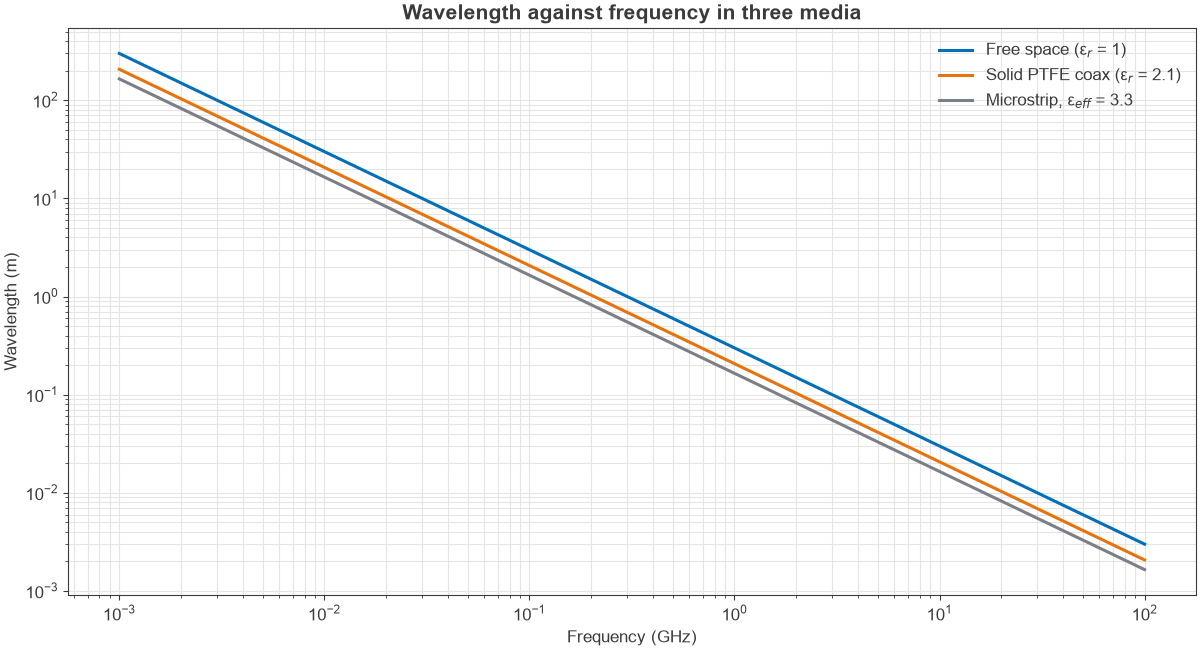
On microstrip the field runs partly in the substrate and partly in air, so an effective value εeff is used, somewhere between 1 and the substrate’s εr. The microstrip calculator gives εeff for a particular trace and stackup. Figure 1 shows the three cases. On log axes each one is a straight line, and the dielectric shifts it down without changing its slope.
In a waveguide the behaviour differs. The guide wavelength is λg = λ / √(1 – (fc/f)2), where fc is the cutoff frequency, so the guide wavelength is longer than the free-space value and grows without limit as the frequency approaches cutoff.
Electrical Length
RF engineers often express physical length as a fraction of a wavelength, or in degrees of phase, where one wavelength is 360°:
θ = 360° × L / λ
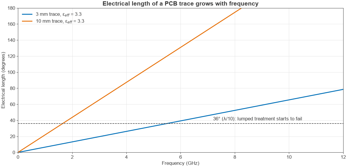
This electrical length is what actually determines circuit behaviour. A common rule of thumb says that a structure shorter than about λ/10 can often be treated as a lumped component, and that a longer one should be treated as a transmission line. The limit is not sharp, and precision designs apply stricter limits.
Because λ falls as frequency rises, the same physical trace grows electrically. Figure 2 shows how quickly that happens. At high frequencies even a component pad or a via is a significant fraction of a wavelength.
Worked Example: A Trace at 5.8 GHz
Take a 5.8 GHz design on a board where microstrip has εeff = 3.3. Three questions come up in practice: how long is a wavelength on the board, how long is a quarter-wave section, and can a 3 mm connecting trace be ignored?
Wavelength in Free Space and on the Board
λ0 = c / f = 299.79 × 10⁶ / 5.8 × 109 = 51.7 mm
λg = λ0 / √3.3 = 28.5 mm, which corresponds to a velocity factor of 0.55
Quarter-Wave Section
A quarter-wave transformer at this frequency is λg / 4 = 7.11 mm long. Sizing it from the free-space wavelength would give 12.9 mm, which is almost twice the correct length.
The 3 mm Trace
The electrical length is θ = 360° × 3 / 28.5 = 38.0°, or 0.105 λ. That just exceeds the λ/10 rule of thumb, and 38° of phase will visibly rotate a reflection coefficient on a Smith chart. The trace reaches λ/10 at about 5.5 GHz, so at 5.8 GHz it must be included in the design.
Where the Relationship Shows Up
Wavelength sets the scale of nearly every RF structure:
- Antennas: a half-wave dipole is about 0.47 to 0.48 λ long after end effects, and antenna gain for a given aperture rises as wavelength shortens.
- Path loss: free-space path loss between fixed-gain antennas rises with frequency, since the receiving aperture of a fixed-gain antenna scales with λ2.
- Matching: stubs and quarter-wave sections have lengths defined in wavelengths, and so they repeat their behaviour at harmonics.
- Filters: distributed microstrip filters use resonators of about λ/2, which become practical on a board only above a few hundred megahertz.
- Phased arrays: element spacing is normally near λ/2, which sets the size of a phased array for a given frequency.
Dimensional tolerance tightens with frequency too. An etching error of 25 µm is negligible at 100 MHz and noticeable at 77 GHz, where the wavelength on a board is little more than 2 mm.
Common Mistakes
The most frequent error is using the free-space wavelength for a line, as the quarter-wave example shows. A similar error is taking the velocity factor of foam cable from a table written for solid dielectric. Another is forgetting that εeff varies slightly with frequency on microstrip, which is a form of dispersion. For precise work, measure the electrical delay of a sample line, or simulate the structure, and do not rely on the formula alone.
Wave speed in the formula refers to phase velocity. Signals carrying information travel at the group velocity. The two are equal in a non-dispersive medium, which is a good approximation for coax, but they differ in waveguide. Properties of electromagnetic waves looks at this further.
Frequently Asked Questions
What is the formula for wavelength from frequency?
Wavelength is λ = v / f. In free space v = c, roughly 3 × 10⁸ m/s, which gives the approximation λ in metres ≈ 300 divided by the frequency in megahertz. In a dielectric, divide that value by the square root of the relative permittivity.
Does frequency change when a wave enters a different material?
No. The frequency stays the same across a boundary. The speed changes, and the wavelength changes in proportion to it.
Why does higher frequency mean shorter wavelength?
The wave travels at a fixed speed in a given medium. If more cycles pass a point each second, each cycle must occupy less distance.
How do I calculate wavelength on a PCB?
Find the effective permittivity of the trace from a calculator or field solver, then use λ = c / (f √εeff). For microstrip on FR-4, εeff is typically around 3, so the wavelength is close to 0.55 to 0.6 of the free-space value.
Related Topics
Continue with the RF fundamentals hub, or read frequency bands in RF design. For practical sizing, see the RF calculators.