Recent advancements in test and measurement capability and related architecture have allowed oscilloscopes to expand into the radio frequency (RF) domain and RF analysis.
The Keysight UXR oscilloscope can simultaneously sample up to 256 Giga-samples per second (GSa/s) on 4 channels, allowing for a functional RF frequency range/bandwidth up to 110GHz. This capability, combined with the performance of a 10-bit analog to digital converter (ADC), allows the UXR to be considered for RF measurements across the spectrum.
However, with such high sample rates, one must pay attention to the memory usage since most oscilloscopes have limited on-board memory. Segmented memory and digital down conversion techniques play an important role in memory efficiency by making meaningful measurements.
Memory efficiency techniques
Contents
Segmented memory – Real-time oscilloscopes make repetitive measurements via an external trigger signal to define an event of interest. Triggering makes meaningful visual measurements that allow the user to see an event of interest based on the trigger criteria.
While this visualization technique doesn’t provide enough memory efficiency for radar pulse analysis, the use of an external trigger for a segmented capture does. Segmented capture allows the user to define the length of a capture interval in terms of samples or seconds along with the number of segments. This enables the user to capture short events of interest of similar length, using the onboard capture memory for meaningful information that meets the user’s criteria.
Photos courtesy keysight technologies
Real-time digital down conversion – The ultra-high sampling rate of modern real-time oscilloscopes is a strength and weakness. On the one hand, ultra-high sampling rates directly capture signals with very high carrier frequencies and wide modulation bandwidths. However, exceptionally high sample rates also consume the onboard memory blazingly fast, reducing the amount of time for capture.
Digital down conversion (DDC) is a relatively common technique used in digitizers that’s made its way into modern digital oscilloscopes. Within the field-programmable gate arrays (FPGAs) and application-specific integrated circuits (ASICs) of the UXR oscilloscope, users can selectively define a center frequency and bandwidth for a measurement, instead of having to directly sample at 2.5x, the highest frequency component of a signal of interest to satisfy the Nyquist frequency (or folding frequency). DDC allows the functional reduction of sample rate from tens to hundreds of GSa/s to hundreds to thousands of MSa/s, enabling the user to capture a longer signal of interest.
Combining segmented capture with DDC allows users to go from capturing a pulsed RF signal over milliseconds, in hope there’s enough information to determine the correct operation of a device, to acquiring pulses over tens to hundreds of seconds to show operation of a system under test.
Measuring challenging signals
Modern radar/electronic warfare (EW) signals are more diverse than past signals. Frequency agility, low probability of intercept (LPI), wider bandwidth, and staggered pulse repetition intervals (PRIs) present measurement challenges because one must now capture pulses over a longer time to see a radar mode or electronic attack (EA) system under test technique to ensure they’re operating correctly. With signals from a technique lasting 30 seconds or more, combined with wider bandwidths, the challenge to effectively capture, analyze, and report results is even more critical.
Theory in practice
Using the Keysight UXR0334A oscilloscope and the 89600 PathWave Vector Signal Analysis (VSA) software, we can visualize the efficiency gains from segmented memory and digital down conversion. In the case below, we will capture and analyze a pulse radar signal of interest with the following parameters:
- Center frequency (CF)= 20GHz
- Pulse repetition interval (PRI) = 1ms
- Pulse width (PW) = 1µs
- Duty cycle = 0.1%
- Calculated with N7660C multiple emitter scenario generation (MESG) application scenario
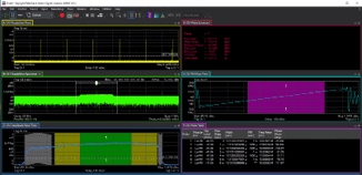
Measurement setup 1 – Direct full sample rate We start the test by running the scope at a full 128GSa/s sample rate and under control by the VSA software. This sample rate satisfies Nyquist given the center frequency of 20GHz (i.e. 20e9 *2 = 40 e9 Samples/second). At this sample rate, we can use 800MSa of onboard memory to capture seven pulses of our signal or a 6.25ms acquisition as shown in Figure 1 (see page 24).
Photos courtesy keysight technologies
This length of capture provides some insight to our example signal; however, it would be difficult to provide insights into long-term pulse stability or proper operation throughout part or all of a scenario. By reducing the sample rate to 64GSa/s, the 20GHz signals can still be captured, but with twice the number of pulses. However, 14 captured pulses are still not enough to verify a pulse radar signal scenario.
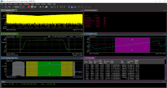
Measurement setup 2: Introducing segmented capture – With a 64GSa/s user setup sample rate, we can now attempt to become more efficient with the oscilloscope memory by using the segmented UXR’s capture feature. In this case, we choose a 1.2µs segment length since our pulses of interest are 1µs long. Given the known PRI of 1ms and the pulse width of 1µs, by capturing a segment length of 1.2µs and not saving samples during the off time of the pulsed RF signal, we can greatly increase memory efficiency.
The segmented capture capability allows for acquisition of up to 6,722 segments/pulses, which results in RF pulse capture >6.7s of target activity time. Compared to the initial 6.25ms, the 6.7s capture has more than a 1,000x increase in capture length, as shown in Figure 2 (see page 24).
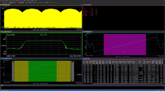
Measurement setup 3: Segmented capture + digital down conversion – Finally, we can incorporate real-time DDC combined with segmented capture to achieve pulse capture across the longest target activity time. Instead of requiring a sample rate based on the center frequency of the signal, we only need to account for the desired capture bandwidth, which in this case would be about 400MHz to capture the signal modulation on the carrier. This allows us to set a sample rate of 800MSa/s on the UXR, capturing more than 70,000 segments/pulses for a total logical capture length of more than 70 seconds (see Figure 3, page 26). Now we can view RF pulses across the course of a typical scenario.
EA, RGPO jamming example
One fundamental technique of jamming against a radar to prevent it from successfully tracking a target is called range gate pull off (RGPO). Consider a situation where an electronic attack (EA) system aboard an aircraft needs to jam a surface-to-air missile radar to prevent the missile from launching or being guided to the aircraft. In this example, we’ll say the distance from the missile launch point to the aircraft is 10km. It would be reasonable to assume that it’ll take approximately 20 seconds for the missile to reach that distance – an important time frame to capture pulses.
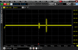
With the RGPO, the aircraft EA system listens to the missile radar, and then exploits the range gates in the radar tracking system by creating false radar return signals. The jammer signals received at the radar receiver are larger than the real radar RF pulse reflections, possibly 10dB to 20dB larger, and slowly move away from the location of the real reflections (see Figure 4, page 26). This causes the range gates in the radar receiver to get pulled off from tracking the real reflections and fooled into tracking the false echo jamming signals. Then the jammer pulses vanish causing the radar to break its track.
There is a cycle of:
- RGPO, radar breaks track
- Radar back to search mode
- Radar re-acquires
- Radar tracks again, then the cycle repeats
RGPO example
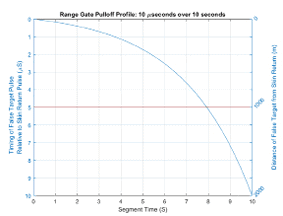
A reasonable scenario example would include 1µsec wide radar pulses and a jammer that creates 1µsec wide false echo RF pulses, which pull from real radar echo signals by around 10µsec across a 10 second period (see Figure 5, page 27). To increase range resolution, pulses have a 400MHz wide chirp. The carrier frequency is 30GHz and PRI is 1msec.
RF pulse capture requirements
To effectively evaluate the jammer RGPO operation, the goal is to capture every radar reflection pulse and jammer pulse over multiple RGPO 10-second cycles. Using full, 128GSa/s sampling, with or without segmented capture, isn’t adequate to capture pulses over one RGPO cycle. Plus, a 5µsec trigger rearm time complicates the use of fixed segments due to missed pulses during the rearm dead time.
Photos courtesy keysight technologies
Variable width segmented capture
A better approach is to use variable width segmented capture with real-time digital down conversion, where an IF trigger senses when a signal is present and only stores samples into segments when it’s present. This eliminates dead time in between pulses and maximizes memory use. Now 800MSa/s in-phase and quadrature-phase (I and Q) data for 640MHz bandwidth to capture the modulation riding on the carrier can be used, extending the oscilloscope memory.
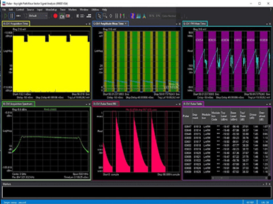
Total scenario time, including potential missile flying time where RF pulses can be captured, has increased significantly. VSA software, with the BHQ radar pulse option, can capture 83,000 pulses in record mode which equates to around 50 seconds of scenario time, more than enough to analyze the 20-second missile flying time as well as multiple 10-second-long cycles of the RGPO engagement including interaction prior to launch. This capture and analysis, shown in Figure 6 (see pages 28-29), includes RGPO process verification by displaying PRI in Trace D.
Conclusion
Modern day real-time oscilloscopes such as the Keysight UXR, allow for exceptional performance with the direct sampling of signals up to 110GHz. The combination of this raw performance with segmented capture and digital down conversion allow for greater insights into signals of interest and long-term trends.
