
Download this article in PDF format.
This article appeared in Microwaves & RF and has been published here with permission.
The proliferation of 4G LTE networks, the deployment of new 5G networks, and the pervasive nature of Wi-Fi are driving a dramatic increase in the number of RF bands that smartphones and other mobile devices must support (Fig. 1). Each band must be isolated using filters to avoid interference that will drain battery life, reduce data speeds, and cause dropped calls.
 1. The highlighted segment within the U.S. radio frequency spectrum of 300 MHz to 3 GHz is the 2-GHz band for mobile devices.
Filters are constructed by coupling basic building blocks, or resonators, to pass the desired frequency while rejecting interfering frequencies.
So, what is a resonator? Various potential resonating structures are utilized to generate filters for different applications (Table 1).
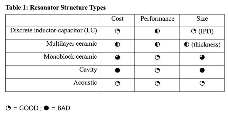
Discrete inductor-capacitor (LC) filters are passive circuits in which the inductor blocks high-frequency signals and conducts low-frequency signals while the capacitor does the opposite. In the case of integrated passive devices (IPDs), which integrate the functions into the printed-circuit board’s laminate, they’re very compact. Although such filter implementations have low passband loss, they don’t reject potential interfering signals in close frequency proximity.
Cavity resonators are expensive and bulky. However, for high-power cellular base stations, these are the filters of choice because of their ability to handle very high-power signals (tens of watts).
Multilayer ceramic filters feature a very low insertion loss, but again, attenuation of potential interfering signals is poor. In addition, relative to IPDs, these devices are large, especially with regards to their height, which limits usage in modules. Such filters are proposed for very high millimeter-wave frequency bands.
From Monoblock Filters to Acoustic-Wave Resonators
Early mobile phones used monoblock ceramic-based filters, which provided the required performance characteristics (Fig. 2). But these phones needed comparatively few filters compared to today’s phones, which can require as many as 40 to 50 filters. Ceramic monoblock filters are now in limited use in modern phones because of their large size and high cost.
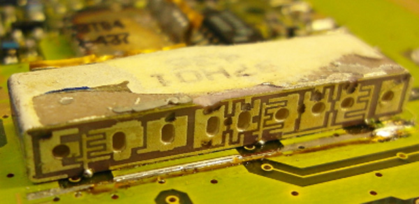 2. Shown is an example of a monoblock filter used in a 1994 Motorola handset.
Modern mobile-phone RF architectures and the explosion in smartphone usage has been enabled by the development of acoustic-wave resonators. These devices combine low cost, small size, and performance characteristics suitable for the frequency ranges and signal power ranges of current smartphones up to 4G.
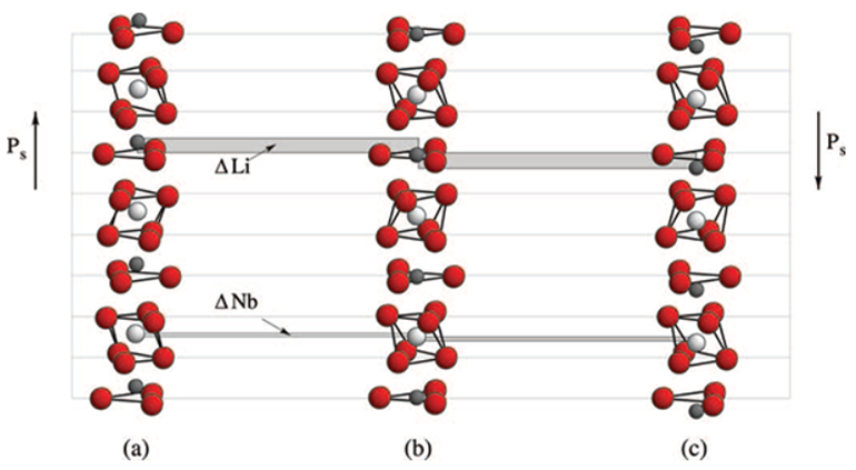
Acoustic-wave resonators based on the piezoelectric effect are very attractive for mobile-phone applications because of their compact size, related to the wavelength of frequencies of interest in a variety of media (Table 2).
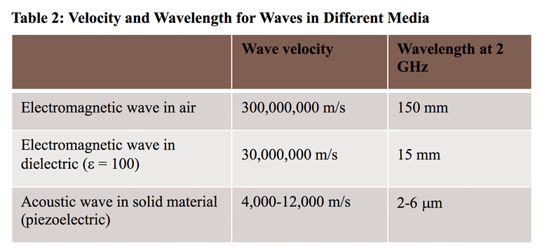
The piezoelectric effect exists in certain crystals due to an asymmetry within the structure. For example, in the lithium-niobate (LiNbO3) lattice shown in Figure 3, the lithium and niobium ions are displaced from the center of the oxygen octahedron.
 3. The lines in this illustration show the asymmetry within the lithium-niobate lattice that leads to a piezoelectric effect.
Consequently, when voltage is applied to this crystal, it will deform mechanically, converting electrical energy into mechanical energy. The opposite occurs when mechanically compressing or expanding such a crystal. Charges form on opposite faces of the crystalline structure, causing a current to flow in the terminals.
An alternating mechanical deformation creates acoustic waves that travel at velocities of 4,000 to 12,000 meters per second. Depending on the details of the metal-piezoelectric structure, acoustic waves can be initiated to flow on the surface or through the bulk of the piezoelectric. In fact, even within the surface-acoustic-wave (SAW) and bulk-acoustic-wave (BAW) categories, there’s a family of acoustic waves with differing properties (Fig. 4).
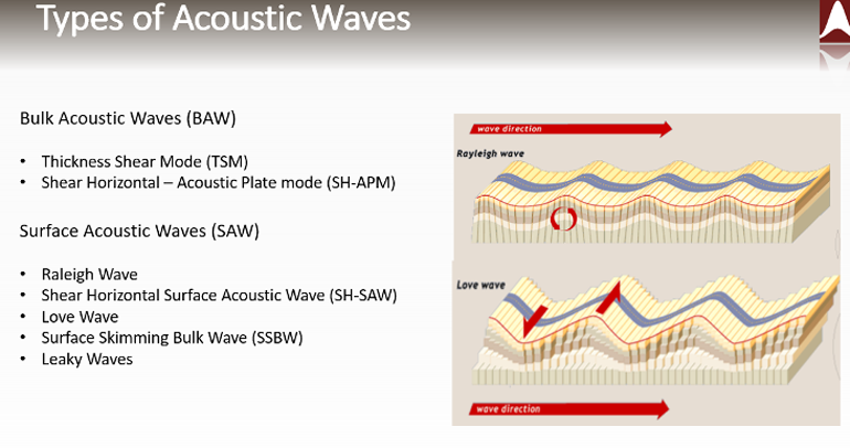 4. This image summarizes the differences between BAW and SAW acoustic waves.
To design a filter, multiple resonators are coupled together to form a passband, often in the form of a “ladder” configuration that alternates series and shunt resonators. Key characteristics of the filter include:
- Bandwidth is often described as the fractional bandwidth because the width of the filter passband/center frequency is expressed as a percentage of the band’s frequency. This is related to a key parameter of the acoustic wave resonator—the coupling coefficient, or k2.
- Frequencies at the lower end of the spectrum require larger resonators. At higher frequencies, dimensions become smaller, which limits achievable yields.
- Loss refers to the reduction in the signal’s strength as it passes through the filter. Low loss maximizes the signal efficiency, which enables reduction of signal power for the transmitted signal. This in turn extends battery life.
- Power levels of mobile signals continue to rise because higher-frequency signals have lower propagation and need more power for coverage and higher speeds. This puts improved reliability demands on filters.
Many of these parameters are a function of design, materials selection, and manufacturing process. However, bandwidth is a fundamental property of the acoustic resonator. In the case of acoustic-wave resonators, each individual resonator has two “resonances”—both resonance and anti-resonance. The frequency separation of these two resonances (characterized as the coupling coefficient, or k2) determines the optimal filter bandwidth.
Below are equations that illustrate key acoustic-wave principles:

where λ is the acoustic wavelength, v is the wave velocity, and f is the resonant frequency.
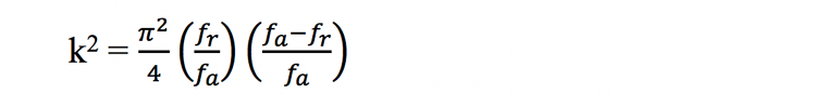
where k2 is the coupling coefficient, fr is the frequency of the resonance, and fa is the frequency of the anti-resonance.
Going from resonator to filter, the maximum achievable bandwidth of an acoustic-wave ladder-type filter is limited by the resonance-anti-resonance frequency separation, which is related to k2 (Fig. 5).
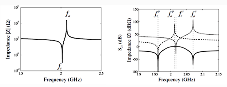 5. An impedance vs. frequency model shows the resonance and anti-resonance for an acoustic-wave resonator (a); by cascading multiple resonators, one may generate a passband filter (solid line, b).
Filter performance is affected by the coupling coefficient (higher coupling increases bandwidth); number of resonators (more resonators increases bandwidth at the expense of loss); quality factor (higher quality factor lowers loss, especially at the band edge); and temperature stability (Fig. 6).
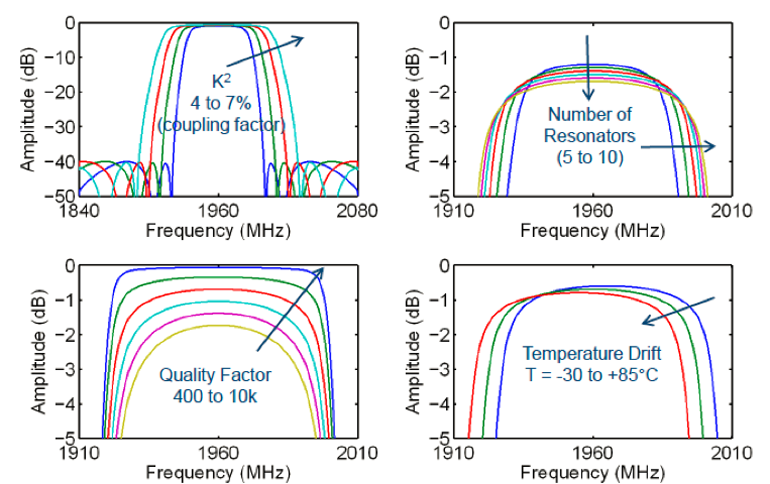 6. Filter performance is affected by coupling coefficient (higher coupling increases bandwidth; upper left), number of resonators (increasing number of resonators increases bandwidth at the expense of loss; upper right), quality factor (higher quality factor lowers loss, especially at the band edge; lower left), and temperature stability (lower right).
Filters for 5G
The key application for 5G mobile phones involves increased streaming video and related streaming services such as gaming or AR/VR—all of which depend on high bandwidth to the device. To dramatically grow wireless broadband capacity and speed, much wider swathes of spectrum, and aggregation of available spectrum, is required. Hence, 5G has new allocations of spectrum that are much wider and at higher frequencies than 4G.
Wide bandwidth is critical to realizing high data rates. In terms of instantaneous bandwidth, this is only available above 3 GHz. Hence, the filter requirements for these new bands are quite different from 4G. 5G requires hundreds of megahertz of spectrum and frequencies above 3 GHz—rather than the tens of megahertz of spectrum at around 2 GHz—as well as filters to protect this bandwidth.
The acoustic-wave resonator used for 3G and 4G can be modified (through doping of the piezoelectric effect and adding external inductors) to increase the achievable bandwidth. However, this comes at the expense of other performance parameters.
Traditional acoustic-wave resonators were developed for previous generations of wireless technology (2G, 3G, and 4G) and the much narrower associated bandwidths. Today’s wireless technology requires new resonating structures optimized from the beginning for the current requirements.
XBAR is a type of BAW acoustic resonator that’s not appropriate for narrower bandwidth filters, yet it’s perfectly matched for 5G (Fig. 7). We’re still in the early days of 5G; high-performance filtering will not yet be needed due to the low user traffic. However, multiple frequencies in close proximity will quickly cause interference issues as more users embrace 5G.
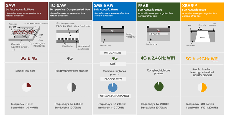 7. Different acoustic-wave resonating structures show the applicability to different generations of wireless networks with relative cost and performance.
Coexistence of 5G and Wi-Fi
5G and Wi-Fi will have a coexistence challenge unlike any other in the history of cellular technology. The n77 and n79 5G bands and the 5-GHz Wi-Fi band are adjacent in frequency with little guard band to separate them (Fig. 8). The new Wi-Fi 6 (802.11ax) standard operates adjacent to the n79 frequency band, which in turn neighbors the n77 band.
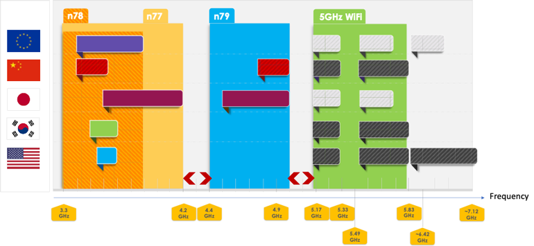 8. Shown here are the small guard bands between 5G and Wi-Fi frequencies.
The coexistence problem has been summarized in a report by industry analyst firm Navian: “The 5-GHz band for Wi-Fi, which is essential for smartphones, sits between the 4.5-GHz and 6- to 7-GHz bands. If these frequencies are to be fully utilized, each bandwidth would need a steep filter. Also, with the n77 and n79 5G bands, high-performance filters for each of these bands would be needed at the same time, since a band gap of 200 MHz is too narrow to be fully utilized.”
As shown in Figure 9, only a 200-MHz separation exists between n77 and n79, and a 150-MHz separation between n79 and 5-GHz Wi-Fi 6 frequencies. Filters for these bands will need to have a large coupling coefficient and high Q, or quality factor. XBAR technology can simultaneously block interfering signals to mitigate interference between the 5G and Wi-Fi bands and pass the maximum bandwidth in each band, thus preventing Wi-Fi signals from bleeding into the n79 data path and vice versa.
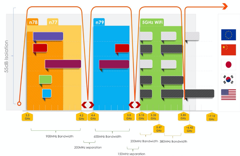 9. Filters are required to prevent interference and enable coexistence/operation for 5G and Wi-Fi bands.
So, what’s the effect of poor filtering on 5G wireless speeds? How will this affect the 5G user experience? Interference will dramatically slow 5G data-throughput speeds, the extent of which will be determined by the extent of the interference. Download time for a 3-GB movie is 34 seconds when using the right 5G filter, but without that filter download time could take 20 minutes or longer (Fig. 10).
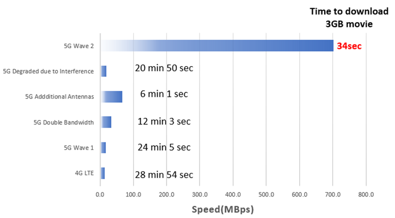 10. These are the download times for a 3-GB file at various wireless bandwidths.
The bandwidth demands of 5G networks are driving a new generation of RF filters that, in turn, requires a new generation of resonators delivering throughput and providing for signal coexistence. Acoustic-wave resonators have become the leading technology, because they have the right range of properties to determine the optimal filter that can be derived for these applications. 5G devices may require up to 100 filters, which makes it critical that the resonator structures are optimized to best match requirements.
Mike Eddy is Senior Marketing Advisor at Resonant.
