>> Electronic Design Resources
.. >> Library: Article Series
.. .. >> Topic: Power Management
.. .. .. >> Series: Driving LED Designs
Download this article in PDF format.
What you’ll learn:
- Two ways to drive and dim RGBW LEDs.
- How a dual buck LED–driver architecture with I2C control can drive multiple LEDs or strings of LEDs with high current and high bandwidth.
- What went into ADI’s demo circuit that includes a GUI for testing the serial communications to an LT3964 LED system.
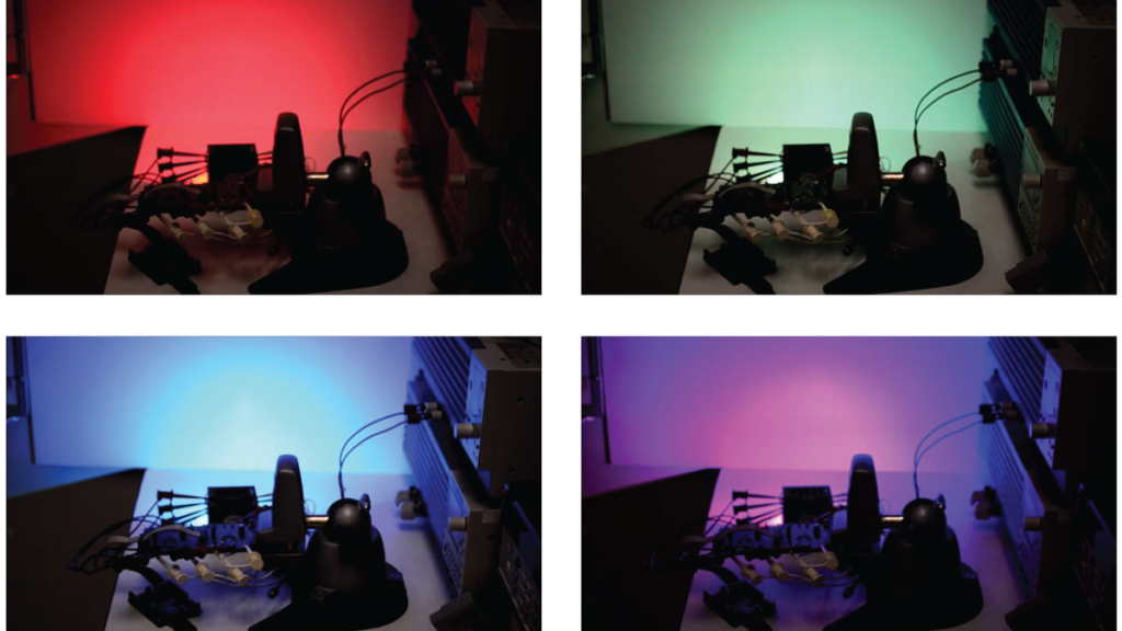
Red, green, and blue (RGB) LEDs can be used in architectural and stage lighting systems to create brightly projected colors—with a white (RGBW) LED sometimes added to the RGB mix to extend the color range in hue, saturation, and brightness (Fig. 1). Regardless of the number of color components, the brightness of each component color must be accurately controlled to achieve predictable colors or compensate for color discrepancies amongst LEDs.
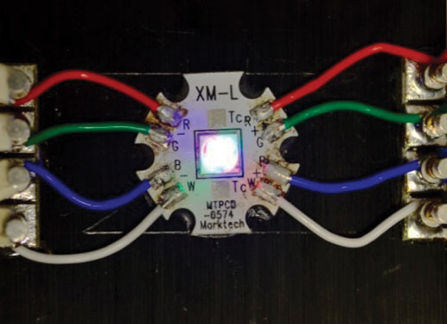
1. A Cree XM-L RGBW high-power LED can be driven by two LT3964 LED drivers for accurate 1:8192 per channel dimming.
The number of available colors depends on the number of resolvable brightness levels of each component color. A few systems offer resolution down to 1/256 (8-bit) of full brightness. Higher resolution is possible and yields more colors (Fig. 2) and control.
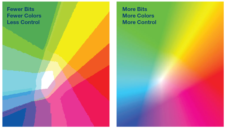
2. Typical driver architectures offer 8-bit color resolution. Implementing a driver that supports 13-bit resolution offers substantially greater color control of high-power LEDs as is required for stage and architectural lighting installations.
The most accurate way to control a wide LED brightness range is with pulse-width-modulation (PWM) dimming control. LED drivers featuring internal PWM dimming clocks and digital registers (to set dimming ratios) are the best option for RGBW systems. For large and complicated systems—those with many different component RGBW LEDs—a serial communications bus enables on-the-fly setting of these registers in digitally enhanced LED drivers.
Figure 3 shows two ways to drive and dim RGBW LEDs. The first, a matrix LED dimmer solution, was, until recently, the best way to digitally control a high–power array of RGBW LEDs. The second, a direct drive solution, is a more accurate, efficient, and lower–ripple solution using four separate, digitally enhanced LED drivers—one for each color (R, G, B, and W). In such a system, the LED current or PWM dimming of each individual LED or string is driven by its own LED driver and control signals (Fig. 2, again).
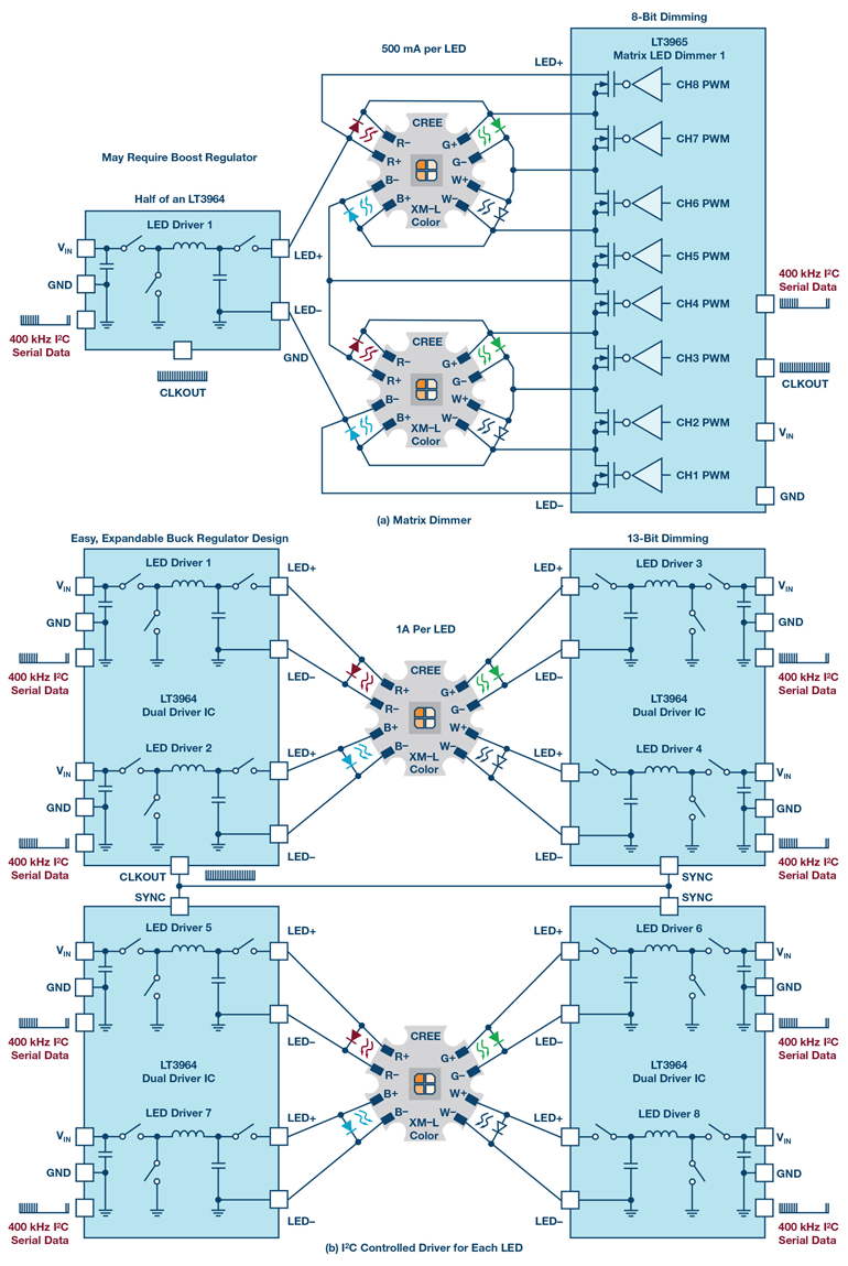
3. There are two ways to power and control color (component dimming) for a large RGBW LED array: a matrix dimmer using the LT3965 (a) vs. a LT3964 direct-drive solution (b). The LT3964 non-matrix solution features improved color control, solution efficiency, and lower ripple.
In the matrix dimmer solution, a single LED dimmer controls the PWM current for up to eight LEDs. The added requirements for this system are a high-voltage line and a low–output capacitor buck LED driver to drive the string of LEDs. The high-voltage rail might require an additional boost regulator and the LED current (from the low output cap buck) can have high ripple.
Lighting systems with a large number of RGBW LEDs require a substantial number of drivers and synchronization of the control signals to those drivers. The highest-performance approach is to directly control each component LED with its own high-performance LED driver. In this method, the PWM dimming and the dc current and voltage of each and every LED can be controlled with the least amount of ripple and greatest predictability. This type of system can be implemented using a dual buck LED driver like the LT3964 and control it via a serial bus.
A dual buck LED–driver architecture with I2C control can drive multiple LEDs or strings of LEDs with high current and high bandwidth via serial communication. Buck regulators are inherently high bandwidth, and having two 36-V, 2-MHz, synchronous, and high–frequency buck LED drivers in a single package, with integrated 2–A switches, simplifies driving multiple channels of high–current LEDs.
The use of serial communications like I2C further simplifies both analog and PWM dimming for the two independent, high–current LED channels supported by each dual buck driver, with up to eight different driver addresses on a single I2C bus. For instance, the 2-MHz, dual 1-A buck LED-driver example circuit in Figure 4 features high efficiency and very small size. It can be altered to power up to 30 V of LEDs per channel from a 34- to 36-V input—as shown in the datasheet—with greater than 90% efficiency.
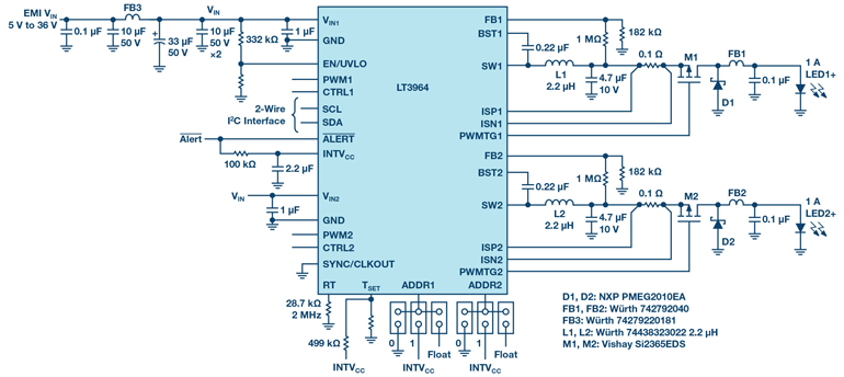
4. The 2-MHz, dual 1-A (or more) buck LED driver demonstration circuit DC2424A features a high-efficiency, compact layout. It can be altered to power up to 30 V of LEDs per channel from a 34- to 36-V input with greater than 90% efficiency.
13-Bit RGBW Color Control
Two LT3964 dual buck drivers are enough to drive a single or a string of RGBW LEDs at 1 A (or higher) (Fig. 5). Although RGBW color is commonly controlled with a 1:256, 8-bit resolution, the driver can accomplish up to 1:8192, 13-bit PWM dimming for each channel combined with 1:10 analog dimming—all controlled by I2C.
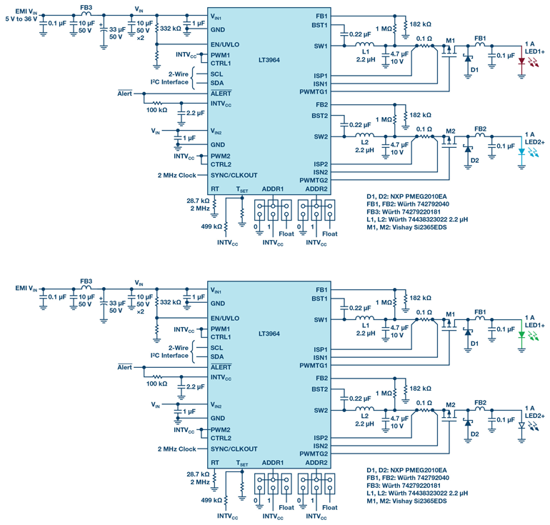
5. Two dual buck drivers (LT3964) can be used together to drive a single or a string of RGBW LEDs at more than 1 A. Each RGBW component color is limited by the dimming resolution, typically 1/256, or 8-bit resolution. Much higher resolution is available with this approach as the system can achieve up to 1/8192, or 13-bit PWM dimming, for each channel combined with 1/10 analog dimming—all controlled by I2C.
This direct-drive approach allows for component RGBW LEDs to differ greatly in brightness and voltage—each channel is completely independent. In this example, a single Cree RGBW LED is driven by four LT3964 channels, each with 1-A output. With a few digital register changes, the brightness and color control extends as far as 1:8192 PWM dimming, and 1/10 analog dimming can provide for each red, green, blue, and white LED. The only real color limitation is the LEDs themselves. In fact, having so much control over color mixing allows for color correction of LEDs if desired.
Syncing for Large Arrays and Low Ripple Operation
The integrated synchronous power switches and 2–MHz switching frequency result in a very small footprint, with a small inductor and ceramic output capacitor for each LED channel. The CLKOUT and SYNC pins of the driver allow for two ICs to synchronize, preventing unwanted beat frequencies, and maintain uniform timing of PWM dimming through serial communications. This eliminates the need for both ICs to be clocked from an external clocking source, simplifying the solution.
Figure 6 illustrates the low-ripple output current of this four-channel, two-IC solution in contrast to the higher-ripple matrix LED dimmer solution referenced above. As shown, the non-matrix, direct-drive approach provides a cleaner LED current waveform than the matrix dimmer solution, which has higher ripple content due to small output capacitor(s).
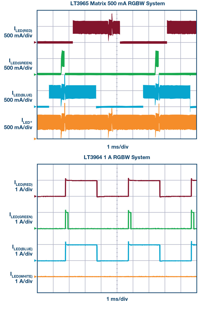
6. The four-channel, two dual buck LED driver circuit has low ripple current and presents a cleaner LED current waveform in contrast to the higher-ripple matrix LED dimmer circuit.
This approach is flexible enough to support systems that require more than four color components. The color gamut for RGB(W) LEDs is shown in Figure 7. When a wider color range is needed, two additional LED elements, such as amber, additional green, or even cyan LEDs, can be added. To drive the additional component colors, simply tie another driver into the same I2C bus.
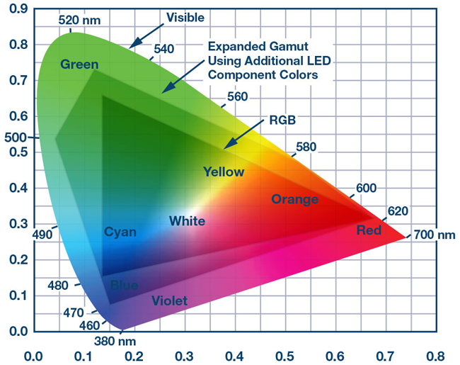
7. The visible color gamut includes colors not available in the RGB color gamut. When an expanded range is required, two additional LED elements, such as amber, additional green, or even cyan LEDs, can be added by simply adding another LED driver tied onto the same I2C bus.
Not all RGBW color–mixing LED systems use monolithic RGBW LED chips. In some systems, separate strings of red, green, and blue LEDs are built into larger, brighter fixtures. Strings of LEDs with different voltages can be driven by each driver stepdown channel, as long as the LED string voltages remain below the input voltage. Strings of up to 30 V of LEDs at 1 A and greater can be driven by a single channel.
I2C Serial Communications
There are two options for controlling analog and PWM dimming with an LED driver like the LT3964. One option is to directly drive the dimming pins with external voltages without using the serial bus. In non-I2C mode, the CTRL1 and CTRL2 pins are driven with adjustable dc voltages for analog dimming of the LEDs; the PWM1 and PWM2 pins are driven with pulsed signals that have duty cycles corresponding to the PWM dimming brightness of the LEDs.
In such a method, the LED PWM frequency is synchronized to the PWM pin inputs and the LED brightness and LED current duty cycle matches the PWM pin input pulses. In larger systems, generating a combination of PWM and analog dimming input signals for a large number of channels can be complex.
The second and potentially more effective method is using a serial communications bus like I2C to control each LED channel or string. The simple two-wire I2C bus is used to control the functions of eight different slave devices from a single master device such as a small microcontroller. Running at speeds of up to 400 kHz, the I2C bus master only needs to generate three bytes to update each of the nine registers on the LT3964 slave devices.
In addition, there are four PWM registers, two analog dimming registers, a status enable register for setting faults, a status register for reading faults, and a configuration register for a few global functions. The three bytes of I2C write commands include the address, subaddress, and data words. Figure 8 demonstrates the different I2C write and read words used in the LT3964 serial communications.
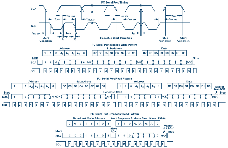
8. The LT3964’s I2C serial communications uses standard I2C write and read words.
The PWM dimming duty cycle and frequency are set by writing to the two PWM dimming registers for each channel (Fig. 9). Figure 10 shows the resulting ILED waveform. It’s straightforward to update up to 16 different channels (two channels each and eight addresses total) with a quick series of I2C writes.
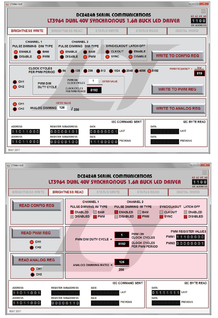
9. The PWM dimming duty cycle and frequency are set by writing to the two PWM dimming registers for each channel. Here, Channel 2 is set to 1:8192 dimming, while Channel 1 is set to 128:256 analog dimming.
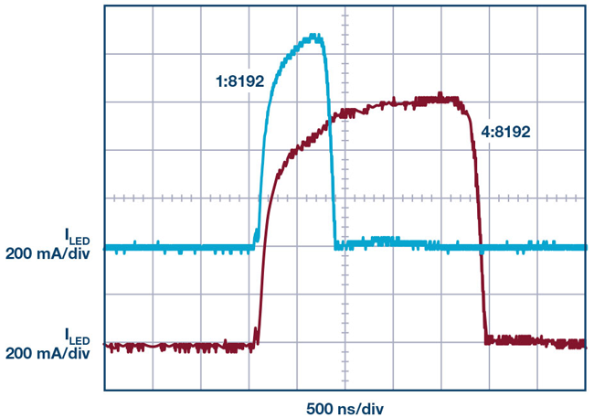
10. ILED waveform showing 1:8192 dimming.
In addition to PWM dimming control, each channel features an 8-bit analog dimming register, which can be updated with a single write command. Analog dimming, if invoked, is typically used only down to about 1/10 dimming. More often, PWM dimming is employed exclusively for RGBW color mixing—it’s sufficient for accurate and repeatable color creation without adding analog dimming. Nevertheless, in systems requiring expanded control, dc LED current adjustment is a useful tool to have in the box.
Other I2C registers include fault protection setting and reading. The LT3964 can report faults for each channel via its ALERT pin and I2C status registers. The faults are only reported if the STATUS registers are individually enabled and a fault has occurred. Open LED, short LED, overcurrent, and overvoltage feedback faults for both channels can be enabled, reported, and read (Fig. 9, again). They can also be disabled and ignored. Fault protection can be a critical part of any serial communications system.
Analog Devices created a demonstration circuit that includes a graphical user interface (GUI) for testing the serial communications to an LT3964 LED system. This circuit uses the QuikEval program when hooked up to a PC through a Linduino One demo circuit (DC2026C) via USB. A quick-start guide for connecting and evaluating the LT3964 demo circuit, DC2424A, is included in the manual for the demonstration circuit. In short, when connected to USB through a DC2026C (Linduino), the LT3964 demo circuit serial communications can be evaluated one command at a time.
Figures 9, 11, and 12 show the GUI pages of the LT3964 demo circuit. On each page, the register elements can be set, then updated over the I2C serial bus. The analog and PWM dimming registers can be updated for each channel, as well as the status enable bits, the global configuration register, and the status enable bits.
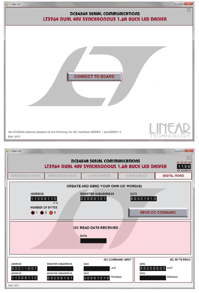
11. The LT3964 DC2424A demonstration circuit can be controlled with a free GUI through QuikEval. On each page, the register elements can be set; then I2C write or read commands are able to be sent with the press of a button through USB and a Linduino DC2026C demonstration circuit. The IC address bits can be set for any address. It’s possible for the GUI to communicate to many LT3964 ICs at once.
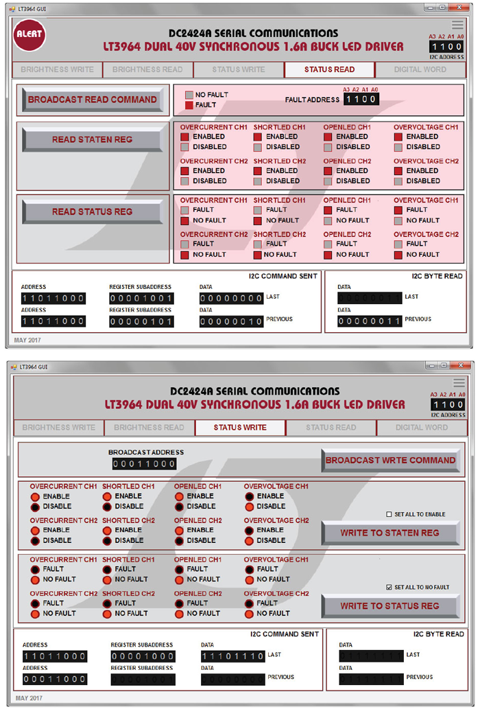
12. I2C registers include fault protection setting and reading. The LT3964 can report faults for each channel via its alert pin and I2C status registers. The faults are only reported if the status registers are individually enabled and a fault has occurred. Open LED, short LED, overcurrent, and overvoltage feedback faults for both channels can be enabled, reported, and read. They also can be disabled and ignored.
For each I2C command sent over the bus, the interface shows the address, subaddress, and data bits generated. The registers can also be read back through the GUI read commands. If a fault occurs during testing, the GUI displays an alert signal in the upper left (Fig. 13) and steps can be taken to examine the nature of the fault and clear the fault though the STATUS and STATUS ENABLE registers.
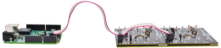
13. Two off-the-shelf DC2424A demo circuits can be connected and used to drive an RGBW LED or string of LEDs with a ribbon cable for I2C control using the GUI and a Linduino.
In a single RGBW system, two separate IC addresses are needed (for four LED components) on the I2C bus. By default, the GUI sends all commands to a default address “1100,” but this can be altered. The address is shown in the upper right of every page and can be changed by clicking on the digits. Thus, the dimming and status registers of up to eight addresses can be controlled and read through the use of the GUI.
In addition, the digital word page of the GUI allows the user to enter any three addresses, subaddresses, and data words manually and send them as an I2C command. Users can consult the datasheet or the other pages of the GUI to generate read and write commands, which are shown in the serial data log at the bottom of the screen.
Figure 13 shows how easy it is to tie together two off-the-shelf DC2424A demo circuits with a ribbon cable for I2C control using the GUI and a Linduino. The SDA and SCL two-wire I2C lines are shared on the bus and the alert signals are tied together with the Linduino ribbon cable. The ALERT pin of each LT3964 is an open collector pull-down, so the master can detect when a fault is present on any IC. When this happens, the GUI displays a red ALERT flag circle in the upper left corner. Once a system fault is detected by the master microcontroller, an alert response protocol is followed to detect and/or clear the fault(s).
Fault Detection and Protocol
The LT3964 has extensive fault protection. It smoothly handles both open and short failures of the LED string as well as overcurrent faults to the output, which aren’t necessarily short circuits. When these faults occur, the ALERT fault flag of the LT3964 asserts. If shared on the same bus, the ALERT bus line gets pulled low (asserted) when any of the LT3964s within a system experience a failure. The I2C communications can be used to locate the IC with the fault first, and then diagnose the fault itself.
The types of faults that may assert the ALERT flag can be set within the status enable register. A fault such as short LED or LED overcurrent can be enabled or disabled here.
After an ALERT assertion, a broadcast read command is used to poll the slave ICs to find out which IC is asserting alert. In the case of multiple alerts, the IC with the lower address sends its address first. The next step is to read the STATUS registers of the faulted address. This should give enough information to diagnose the fault and clear the fault flag. If the fault flag remains asserted, another broadcast read command can check for subsequent faulted addresses.
When the faulted addresses and the status registers have been read, the faulted status bits can be cleared by sending a write command to the faulty address. If the fault doesn’t clear, it can be reported that service is needed, or the fault can be ignored by turning off the status bit enabling the fault.
Conclusion
A dual buck LED driver with I2C serial communications like the LT3964 can be used in computer-controlled lighting systems featuring a large number of high-power LEDs and LED channels. Two drivers are enough to drive a single RGBW LED—or string of RGBW LEDs—at 1 A with accurate and precise dimming to produce predictably repeatable color content (Fig. 14).

14. Complete digital control over high power RGBW LEDs using the LT3964 dual buck driver with I2C serial communications.
Evaluation is easy using the off-the-shelf DC2424A demo circuit and free QuikEval PC-based software. The LT3964’s shared I2C two-wire serial communications bus is able to control up to eight addresses and 16 switching channels. Its wide input voltage range and compact, but powerful, integrated synchronous stepdown switches can be used for up to 30 V of LEDs on each channel. Switching frequency capability up to 2 MHz enables compact designs and small inductors, which is important when the driver circuit is duplicated throughout large-scale systems that feature numerous LEDs and channels.
>> Electronic Design Resources
.. >> Library: Article Series
.. .. >> Topic: Power Management
.. .. .. >> Series: Driving LED Designs
