Abstract
Contents
With optical spectral marks equally spaced by a frequency in the microwave or the radio frequency domain, optical frequency combs have been used not only to synthesize optical frequencies from microwave references but also to generate ultralow-noise microwaves via optical frequency division. Here, we combine two compact frequency combs, namely, a soliton microcomb and a semiconductor gain-switched comb, to demonstrate low-noise microwave generation based on a novel frequency division technique. Using a semiconductor laser that is driven by a sinusoidal current and injection-locked to microresonator solitons, our scheme transfers the spectral purity of a dissipative soliton oscillator into the subharmonic frequencies of the microcomb repetition rate. In addition, the gain-switched comb provides dense optical spectral emissions that divide the line spacing of the soliton microcomb. With the potential to be fully integrated, the merger of the two chipscale devices may profoundly facilitate the wide application of frequency comb technology.
INTRODUCTION
Self-referenced optical frequency combs (OFCs) based on femtosecond pulse lasers have provided phase-coherent links between the optical domain and the radio frequency (RF) or microwave domain (1, 2). On the one hand, these mode-locked lasers can synthesize frequencies that span from extreme-ultraviolet (3) to mid-infrared ranges (4) with RF/microwave references such as atomic clocks (5–7) or stable masers (8, 9), thus revolutionizing the fields of optical metrology and spectroscopy (10). On the other hand, owing to the development of the frequency division technique that transfers the spectral purity of an optical reference to the microwave domain with the benefit of a divided phase noise spectral density, the photodetection of pulse trains has been used to synthesize microwaves with the lowest phase noise levels achieved (11, 12). Yet, despite their exquisite performance, to date, the use of mode-locked laser-based OFCs is mostly limited to the laboratory environment due to the bulky sizes, the high power consumption, and their delicate structures.
To overcome the difficulties of out-of-laboratory usage of traditional OFCs and to meet the urgent demand of low-cost, portable, and power-efficient comb sources that are suitable for field-deployable time keeping, navigation, and high-bitrate telecommunication, alternative OFC techniques have rapidly advanced in the past decade (13–15). Among them, two approaches have attracted significant research interest. The first is the microresonator frequency combs based on dissipative Kerr solitons (DKS) (16). Also referred to as soliton microcombs, these OFCs are generated with self-organization of localized light structures in Kerr microresonators driven by continuous-wave (CW) lasers. With their high repetition rates and intrinsic high coherence, soliton microcombs have been applied in ranging (17, 18), low-noise RF generation (19), and integrated clocks (20). The second approach uses semiconductor gain-switched lasers (GSLs) to create laser pulse trains by rapidly switching the gain above and below the lasing threshold (21, 22). With the gain switching frequency being externally controlled by a microwave signal, these pulsed lasers are highly flexible and tunable in both the repetition rate and the emission wavelength (23–26). Successful applications of GSLs have been demonstrated in quantum key distribution (27), random number generation (28), and coherent optical communication (29, 30). However, compared to mode-locked laser OFCs, GSL OFCs have very narrow optical spans that are usually of a few nanometers. Moreover, GSL OFCs rely on auxiliary microwave frequencies for pulse repetition rates, which transfers the noise contained in the microwave source into every comb tooth with a multiplication. For DKS microcombs, although self-referencing with broadband spectra has been achieved (31, 32), the typical line spacings of a few hundred gigahertz to a few terahertz are beyond the detection bandwidth of conventional electronics, which is undesirable in many applications. Recently, a dual-microcomb scheme was demonstrated (32), using a second microcomb with a small line spacing to bridge the wide gap (∼1THz) of an octave spanning microcomb (33). Despite its successful implementation in optical frequency synthesis, such a scheme requires sophisticated active locking systems, and the fixed line spacing of the adopted microcomb could limit the wider application when a varied line spacing is needed.
In this work, we present a novel frequency division scheme by injecting a soliton microcomb with a repetition frequency of frep into a distributed feedback (DFB) laser that is operating in the gain switching mode. By optical injection locking the DFB laser with the microcomb and actively locking the gain switching frequency (fgs) to a subharmonic frequency of the soliton repetition rate (i.e., fgs = frep/n, with n being a positive integer), the DFB laser emits a frequency comb that spans nearly 50 nm, with a repetition frequency that is a perfect fraction of the soliton repetition rate. In contrast to the conventional optical frequency division technique that transfers the stability of an optical frequency into the microwave domain, our scheme transfers the spectral purity of the cavity soliton oscillator at frep to the phase-locked fgs with a reduction of a factor of n2 in the phase noise spectrum, even when frep is too high to be directly measured with conventional electronics.
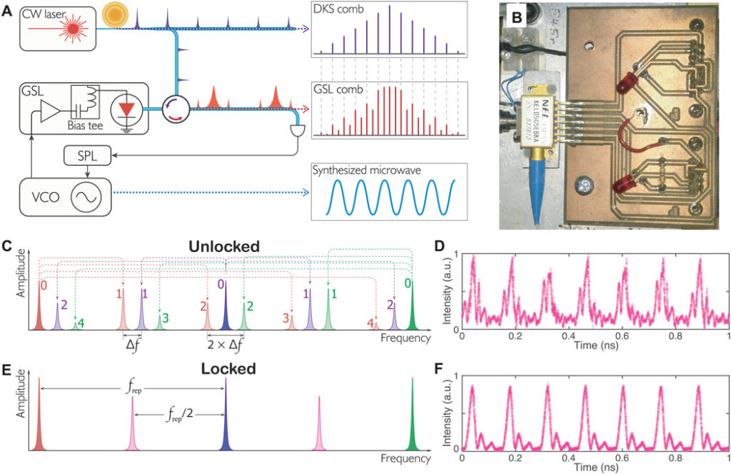
Figure 1A depicts the principle. A soliton microcomb generated by a CW laser–driven microresonator is injected into a GSL to provide the main comb lines and the phase coherence of the lasing field. In the meantime, the semiconductor laser is gain-switched at a frequency close to the subharmonic frequencies of the microcomb repetition rate frep. The gain switching frequency is produced by a tunable signal generator such as a voltage-controlled oscillator (VCO). In the frequency domain, gain switching gives rise to sidebands around main comb lines (i.e., the emissions that are optical-injection-locked to the master microcomb), and the beating between the sidebands and other main comb lines or their sidebands essentially causes laser intensity fluctuations that can be directly used as an error signal to implement subharmonic phase locking [SPL; see the Supplementary Materials for the physical model based on the laser rate equations (25, 34) and the Lugiato-Lefever equation (35)]. Figure 1C illustrates the SPL mechanism. The GSL spectral components denoted by the number 0 are the main comb lines. Gain switching at approximately frep/n (n = 2 in the figure) generates multiple sidebands (whose orders are shown by the corresponding numbers). These sidebands produce multiple beat signals at frequencies of Δf and its harmonics, which correspond to an intensity-modulated signal in the time domain (see the Supplementary Materials for the simulation of the error signals). The latter can be directly used for the control of the VCO frequency for the SPL. Once the SPL is activated, the beat frequencies of ∆f and its harmonics vanish, as the intensity error signal is locked to a constant level. Consequently, fgs is controlled to be an exact fraction of frep, which is illustrated in Fig. 1E. Here, we note that the SPL cannot be implemented with the sideband generation method via electro-optic modulation (36) due to the lack of intensity modulation–induced error signals. Figure 1 (D and F) shows the experimentally measured GSL intensities in the time domain when the SPL is off and on, respectively. With the SPL being activated, the gain switching frequency is feedback-controlled to be exactly half of the soliton repetition rate of 14.09 GHz, and the emitted pulse train is highly coherent as depicted in Fig. 1F, exhibiting substantially reduced intensity jitter.

(A) The conceptual illustration of the scheme. The VCO is controlled by the SPL servo, outputting microwave frequency that is a subharmonic of the soliton repetition rate. (B) A photograph of the DFB laser used in this work. (C) Illustration of the gain-switched comb when the SPL is off. Multiple frequencies caused by the beating between sidebands of different microcomb teeth are generated. (D) The output of a soliton-injected GSL (with the SPL off) measured by an optical sampling oscilloscope. a.u., arbitrary units. (E) Illustration of the subharmonic phase–locked scenario in the frequency domain. (F) Output of the GSL in the time domain when it is subharmonic phase–locked to the soliton repetition rate (14.09 GHz). Photo credit: Wenle Weng, EPFL.
RESULTS
In the first experiment (see Fig. 2A for the setup), a crystalline magnesium fluoride (MgF2) whispering gallery mode resonator with a cavity free spectral range (FSR) of 14.09 GHz is used to generate the DKS. The pump-resonance detuning is stabilized with the Pound-Drever-Hall (PDH) sideband locking technique (37). The soliton microcomb is amplified to an average power of 5 mW with an erbium-doped fiber amplifier before it is injected into the GSL. The GSL outputs an average power of ∼1 mW, half of which is sent to an optical spectrum analyzer (OSA) for spectrum acquisition. The other half of the light is registered by a photodetector with a bandwidth of ∼5 MHz, and the photodetector voltage is used as the error signal to implement the SPL. In this proof-of-principle demonstration, we use a microwave signal generator to generate fgs. The error signal is fed back with a proportional-integral control servo to the frequency modulation port of the signal generator. To suppress the long-term drift of frep that is mainly caused by the temperature drift of the microresonator, we use the dc level of the SPL servo correction signal as the error signal to control the pump laser intensity with a power servo whose control bandwidth is ∼10 Hz. One should note that this power servo is not necessary for the SPL system and that fgs can be effectively locked to the subharmonic frequencies of frep even when frep drifts for more than 1 MHz (see the Supplementary Materials for the long-term frequency instabilities). Two gain switching frequencies at frep/2 (7.05 GHz) and frep/3 (4.70 GHz) are applied, respectively. Figure 2B presents the optical spectra of the amplified microcomb and the GSL OFC. The soliton-injected GSL spectra show prominent emissions at frequencies around 1548 nm, with a span of a few nanometers. The comb spectra span over nearly 50 nm with less intensive teeth that exhibit perfect repetition rate division of the DKS microcomb, despite the fact that amplitude nonuniformities are presented (see the Supplementary Materials for the possible reasons). Figure 2C shows the error signals generated by the photodetector (PD2) for the SPL servo. With fgs at 7.05 GHz, the error signal shows great contrast. For fgs = 4.70 GHz, the contrast of the error signal deteriorates as the GSL pulse width increases with decreased gain switching frequency, leading to reduced sideband intensities. Such inefficiency of gain switching can also be observed from the significantly lower amplitude of the gain switching sidebands in the comb spectrum (see the inset of Fig. 2B). Still, owing to the excellent relative intensity noise (RIN) performance of the GSL (38), the SPL is robust and can be sustained indefinitely.

(A) Experimental setup. A fiber Bragg grating (FBG) and a circulator are used to separate the pumping external cavity diode laser (ECDL) from the solitons. A photodetector (PD1) and an electro-optic modulator (EOM) are used to produce PDH signals to lock the laser-resonance detuning. Half of the GSL power is registered by a photodetector (PD2) to produce subharmonic locking error signals. A servo locks the gain switching frequency to be an integral submultiple of frep via frequency modulation (FM) of the signal generator. Simultaneously, the dc output of the servo is used as an error signal to stabilize frep through amplitude modulation (AM) of the pump laser power with an acousto-optic modulator (AOM). (B) The optical spectra of the microcomb and the soliton-injected GSL gain-switched at frep/2 and frep/3, respectively. The inset shows an enlargement of a portion of the spectra. (C) The error signals generated by PD2. The dashed line indicates the locking point. (D) The power spectra of the soliton-injected GSL when the SPL is on (red) and off (blue). (E to G) The spectra of DKS frep and the phase-locked gain switching frequencies at frep/2 and frep/3, respectively.
We measure the spectral qualities of the synthesized fgs signals and frep that is generated by the photodetection of the DKS train with a fast photodetector (bandwidth of ∼30 GHz). Figure 2 (E to G) shows these signals obtained with an electrical spectrum analyzer. In Fig. 3, we present the phase noise spectra of these signals. Within the SPL servo control bandwidth of ∼10 kHz, the phase noise levels of the synthesized fgs are exceptionally lower than the intrinsic phase noise levels of the signal generator. Moreover, they are lower than that of frep by 6 and 9.5 dB, respectively. Such a reduction corresponds to a factor of n2 improvement with n = 2 for 7.05 GHz and n = 3 for 4.70 GHz, showing the expected benefit of frequency division. Reaching a level below −115 dBc/Hz at the offset frequency of 1 kHz, the low-phase noise of the synthesized microwaves is already comparable with, or better than, the state-of-the-art performance of parity time symmetric optoelectronic oscillators (39, 40), microphotonic microwave synthesizers based on stimulated Brillouin oscillations (41), and electro-optical frequency division (42).

The 14.09-GHz DKS frep is generated by photodetection of the soliton train. The synthesized signals at 7.05 (frep/2) and 4.70 GHz (frep/3) are output by the frequency-modulated signal generator when the SPL is activated. The servo has a control bandwidth of ∼10 kHz, causing the rising noise level around that frequency. Within the control bandwidth, the noise levels of the two synthesized microwaves are lower than that of frep by 6 and 9.5 dB (the dashed lines with a slope of f−2 are plotted for visual guidance). At frequencies above 100 kHz, the phase noise of the synthesized microwaves are identical to the levels intrinsic to the free running signal generator because of the servo’s limited bandwidth. The inset shows a photograph of the MgF2 resonator. Photo credit: Tobias Herr, EPFL.
Next, we apply our frequency division scheme to detect and divide a high soliton repetition rate that cannot be conveniently measured with our electronic instruments. We use a silicon nitride (Si3N4) microring resonator with an FSR of ∼100 GHz for DKS generation. The gain switching is implemented at three different frequencies of 16.82, 10.09, and 6.73 GHz, corresponding to a division factor of n = 6, 10, and 15, respectively. The amplified DKS microcomb spectrum and the GSL spectra are displayed in Fig. 4 (A and B). The GSL OFC shows equally spaced teeth filling the gaps between the microcomb teeth. The GSL comb teeth are well resolved with a resolution limited by that of the OSA, showing that the GSL maintains excellent coherence (see the Supplementary Materials for corroborating optical heterodyne measurement). In Fig. 4C, we plot the phase noise spectra of the synthesized fgs signals, based on which we infer the phase noise of the 100.93-GHz frep. Here, we note that the phase noise performance of the synthesized microwaves is similar to that of the microwaves derived from the recently developed X- and K-band Si3N4 soliton microcomb oscillators (43). This phase noise level, which is much higher than the fundamental thermal noise limit (44), is attributed to technical noise such as ambient temperature fluctuations, pump laser phase noise, and RIN (43). With progress on the microresonator fabrication process and technical noise suppression in the future, we expect the phase noise to be considerably improved to enable on-chip low-noise millimeter-wave and microwave synthesizers based on GSL frequency division.

(A) From top to bottom: the optical spectra of the amplified soliton microcomb and the GSL with gain switching rates of frep/6, frep/10, and frep/15, respectively. (B) The enlargement of the comb spectra from 1546 to 1550 nm. (C) The phase noise spectra of the synthesized microwave signals. The blue dotted trace is the phase noise level of the 100-GHz frep inferred from the measured phase noise levels of the synthesized signals. The trace is not plotted above 30 kHz because of the limited control bandwidth of the SPL servo. The inset is a photograph of the Si3N4 microresonator.
DISCUSSION
In summary, built upon the marriage between soliton microcomb and gain-switched comb, we present a hybrid photonic system that not only yields a broadband frequency comb with a line spacing equal to the divided soliton rate but also synthesizes low-noise signals in the microwave domain. In contrast to traditional optical injection locking method that uses a CW laser as the master, our scheme injection locks a semiconductor laser to the entire microcomb, transferring both the carrier phase coherence and the soliton repetition rate spectral purity to the GSL. As a result, with active control, the GSL can generate additional comb teeth that are fully coherent and equally spaced, thus facilitating the application of high–repetition rate microcombs in metrology and spectroscopy. In addition to low-noise microwave synthesis, this technique can also be used to measure the phase noise of pulse repetition rate that is beyond the detection bandwidth of conventional electronic devices. Moreover, with the optical pulse injection locking scheme, we are able to carry out OFC repetition frequency multiplication with the GSL (see the Supplementary Materials for more information). The versatility of the configuration highlights the joint effort by different OFC technologies. As both comb devices are chip-based, future endeavor can be made to the development of a fully integrated miniaturized architecture that could find extensive applications in demanding environments.
MATERIALS AND METHODS
MgF2 resonator
The MgF2 resonator was fabricated by diamond turning a crystalline cylindrical blank and subsequent surface polishing. The intrinsic linewidth of the resonance is ∼100 kHz, corresponding to an intrinsic quality factor (Q) of ∼2 × 10⁹. The second-order dispersion coefficient at 1550 nm is approximately 2 kHz. To generate solitons, a tapered fiber is used to evanescently couple light into and out of the resonator. The pump laser is amplified to ∼100 mW. Using the PDH sideband locking technique, the pump-resonance detuning is locked at 6 MHz.
Si3N4 resonator
The Si3N4 microring resonator was fabricated with the photonic Damascene process (45). The coupling section is designed to operate close to the critical coupling regime for 1550 nm. The loaded linewidth of the resonance is ∼30 MHz, corresponding to a loaded Q of ∼6.7 × 10⁶. The dispersion parameter is measured to be ∼1 MHz. Fiber lenses were used to couple light into and out of the waveguide that is evanescently coupled to the microring. The pump laser power is 80 mW. The pump-resonance detuning is locked at 300 MHz with the PDH sideband locking technique.
Semiconductor GSL
The laser used for generation of the GSL OFC is a commercially available DFB laser (NTT Electronics) encased in a seven-pin butterfly package, without an output isolator. The laser had a threshold current of 10 mA and 18-GHz modulation bandwidth. The gain switching is achieved by combining, via a bias tee, the dc bias current of ∼50 mA with an RF signal (after amplification with an RF amplifier) from a microwave signal generator (Rohde&Schwarz SMB100A). A fiber circulator is used to inject the soliton microcomb into the laser. The polarization state of the injected light was adjusted by a fiber polarization controller to optimize the contrast of the error signal for the SPL.
- Copyright © 2020 The Authors, some rights reserved; exclusive licensee American Association for the Advancement of Science. No claim to original U.S. Government Works. Distributed under a Creative Commons Attribution NonCommercial License 4.0 (CC BY-NC).
