
>> Electronic Design Resources
.. >> Library: Article Series
.. .. >> Topic: Power Management
.. .. .. >> Series: Driving LED Designs
Members can download this article in PDF format.
Automobile LED headlight clusters combine high and low beams, daytime running lights, and sometimes signal and clearance lights into a single headlight cluster. The components of the cluster can have vastly different driver requirements, including voltage and current requirements, topologies, power levels, or unique dimming functions.
Meeting the range of requirements usually means employing separate driver solutions. Using multiple drivers not only complicates bills of materials (BOMs) and production, it can also make it difficult to meet electromagnetic-interference (EMI) standards. Each additional driver adds its high-frequency signals to the EMI mix, complicating EMI qualification, troubleshooting, and mitigation.
Although the headlight cluster for each automobile make and model may be outfitted with a creative variety of LED currents and voltages, they commonly top out at 30 W total. With that in mind, there should be a number of drivers that satisfy the power and feature requirements of every string in the cluster. There are not.
Using a buck-boost topology, such a driver needs to take the relatively wide battery voltage range and convert it to the wide variety of string voltages. It needs to be small and versatile, fit easily into the space constraints of the cluster, and produce little EMI to minimize R&D efforts and eliminate the need for costly metal-shielded EMI cases. It should also be efficient.
Controller Solution
Contents
A 2-MHz buck-boost controller for LED current regulation like the LT8391A enables the use of a single, small inductor and small overall solution size for high-power LED applications. Unlike monolithic converters, whose power switches are contained within the IC package, controllers can drive external power switches with much higher peak currents, e.g., 10 A. Such peak currents would burn up the small IC packages of typical integrated converters.
In contrast, a controller with external 3- × 3-mm synchronous MOSFETs is able to deliver much higher power. These MOSFETs can be arranged in tight quarters with hot-loop capacitors for very low EMI. The unique peak-switch, current-sense amplifier architecture places the sense resistor next to the power inductor, which is outside of the critical input and output hot loops—reducing EMI. Optional spread-spectrum frequency modulation (SSFM) further reduces the controller’s EMI.
Figure 1 shows the efficiency of a 2-MHz buck-boost LED driver that reaches as high as 93% efficiency with EMI filters and gate resistors (Fig. 2). Efficiency is 1% to 2% higher with the optional EMI components removed. With small 3- × 3-mm MOSFETs and a single high-power inductor, the temperature rise for this converter is low, even at 24 W.
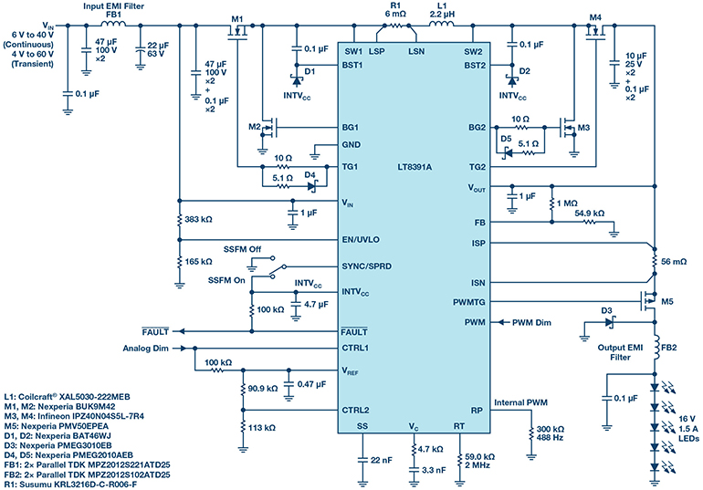 1. The LT8391A 2-MHz, 16-V, 1.5-A automotive buck-boost LED driver passes CISPR 25 Class 5 EMI.
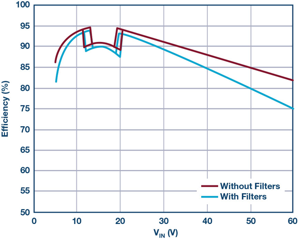 2. Efficiency of LED driver solution in Figure 1. Measurements made using 16-V, 1.5-A demonstration-circuit DC2575A LED driver with and without optional EMI components.
At 12-V input, no component rises more than 25°C above room temperature. At 6-V input, the hottest component rises less than 50°C with a standard four-layer PCB and no heat sink or airflow. It continues to run at full 24-W load in the face of input transients down to 4.3 V; or reduced load current via analog or PWM dimming when the input drops for long periods. The 8- to 10-A sense resistor makes this high power at low VIN possible.
The LT8391A in the example includes the PWM dimming features and open LED fault protection. This synchronous buck-boost regulates current through a string of LEDs with a voltage that may or may not lie within the input-voltage range, such as the 9- to 16-V car battery or a truck battery (18 to 32 V). It can run down to 4.0-V cold crank input and withstand up to 60-V input transients. Such LED drivers are able to provide up to 2000:1 pulse-width-modulation (PWM) dimming ratio at 120 Hz and use their internal PWM dimming generator for up to 128:1 accurate dimming ratio without the need for an externally supplied PWM clock (Fig. 3).
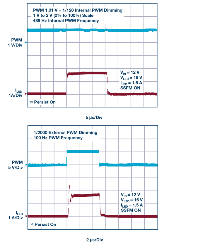 3. PWM dimming using internal and external PWM options—1% and 0.05%, respectively.
CISPR 25 EMI for Automotive Applications
LED drivers for automotive headlights must meet specific standards, such as using AEC-Q100 components and achieving CISPR 25 Class 5 radiated EMI standards. SSFM reduces EMI, and it runs flicker-free simultaneously with PWM dimming. Large LC filters aren’t needed for 2-MHz converters and only small ferrite beads are used for high-frequency EMI reduction. Overall size can be reduced because of the small inductor and small input and output EMI filters.
Automotive EMI requirements aren’t easily met by high-power converters. High-power switches and inductors, placed on large PCBs next to large capacitors, can create undesirable hot loops, especially when a large sense resistor is included. In the case of the LT8391A, its buck-boost architecture removes the sense resistor from both the buck and boost switch-pair hot loops, enabling low EMI.
Figures 4 and 5 show measured EMI of the 24-W LED driver in Figure 1. Despite this buck-boost controller’s 2-MHz operating frequency and 24 W of power, it passes CISPR 25 Class 5 radiated and conducted EMI. Class 5 is the most stringent requirement and the goal of most automotive EMI testing. Converters that can’t pass Class 5 EMI either get designed out of automotive circuits or must be encased in large metallic EMI shields. Even if the bulkiness of the shield doesn’t cause assembly issues, adding them is costly.
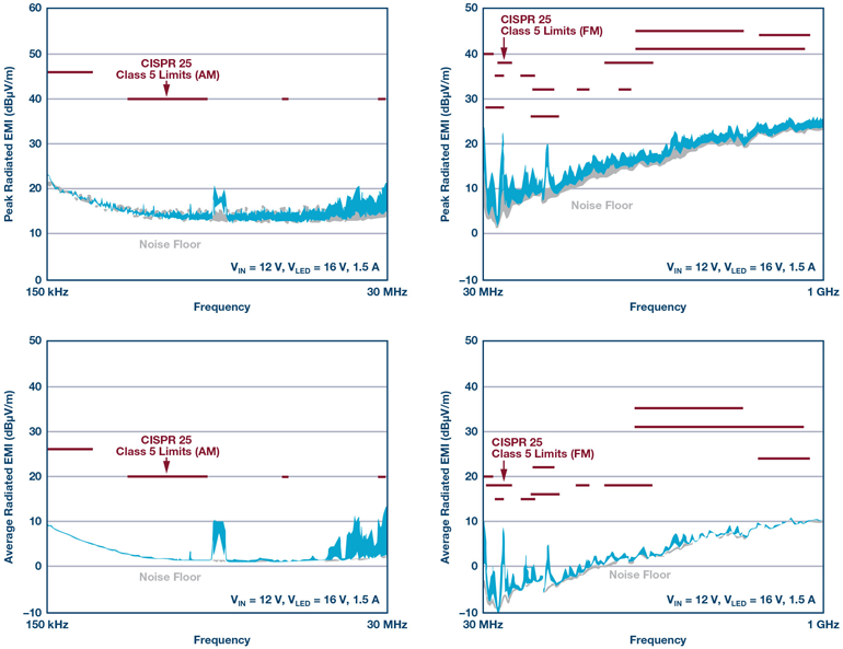 4. Demonstration-circuit DC2575A passes CISPR 25 Class 5 automotive radiated EMI.
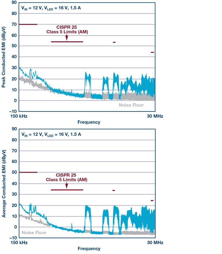 5. Demonstration-circuit DC2575A passes CISPR 25 Class 5 automotive conducted EMI.
Buck-Boost for Multi-Beam Applications
LED headlight clusters can be both innovative and artistically creative. High beams and low beams can be wrapped up with nifty and distinctive daytime running lights (DRL). Because the daytime running lights are only needed when high and low beams are off, it’s possible for a single LED driver to power either the high- and low-beam LEDs or the DRL. This only works, though, if the LED driver has a flexible input-to-output ratio and is able to both step-up and step-down the input-to-output voltage. A buck-boost design satisfies this requirement.
Figure 6 shows a multi-beam application that can drive LED string voltages ranging from 3 to 34 V. Thus, it’s able to drive both a low-beam string and create a high beam by adding LEDs to the low beam string. The same driver switches over and drives a higher-voltage, yet lower-current, DRL.
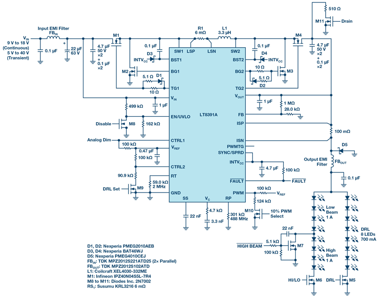 6. Multi-beam LED headlight cluster solution for low, high, and DRL lights.
Switching from low-beam-only LEDs to a low-/high-beam combo string generates no spike on the output voltage or LED current as shown in Figure 7a. The LED driver can transition between boost, four-switch buck-boost, and buck regions of operation smoothly.
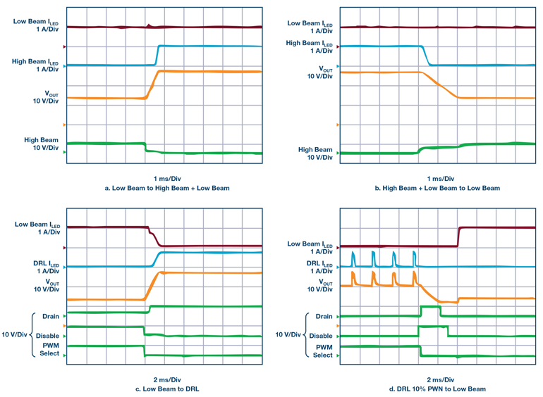 7. Waveforms show smooth switchover between high + low, low, and DRL LED strings for the multi-beam application in Figure 5.
Changing from a small number of LEDs to a high number of LEDs without an LED spike can be challenging for a converter, but this multi-beam circuit does it with ease. Switching back from high and low beams to just low beams is also very clean, without any harmful LED spikes (Fig. 7b).
The same is true when switching to and from the DRL string. Figure 7c demonstrates how the low beam is turned off and the DRL is smoothly connected to the output capacitor. Even the LED current is changed from 1 A (high and low beams) to 700 mA (8 LEDs DRL) without any issues. Other trim or signal LEDs could be added in as well, and the DRL can be blinked as a signal light. Figure 7d shows how the DRL can be PWM dimmed with the internally set PWM generator and then switched over smoothly to low beams when darkness falls.
Automotive environments require robust solutions in the face of short-circuits and open LEDs. Short- and open-circuit conditions are safely handled by the multi-beam solution shown in Figure 6 and reported via the converter’s fault flag.
FE and QFN Packages Fit Tight Spots
To fit in the tight space constraints of a vehicle, LED drivers must be housed in small packaging (Fig. 8). In addition, thermally enhanced GND pads allow for power dissipation of the internal INTVCC LDO from higher voltages.
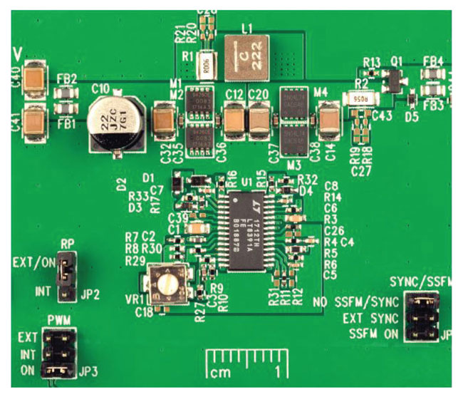 8. This compact solution drives 16-V LEDs at 1.5 A.
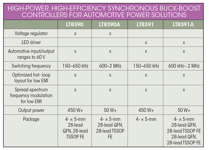
Buck-boost LED driver controllers like the LT8391A operating at 2 MHz are well-suited for 60-V power LED strings in automotive headlights (see table). A low-EMI four-switch architecture and SSFM enable developers to meet stringent CISPR 25 Class 5 EMI requirements.
Operating at a high switching frequency enables LED drivers to operate above the AM band, requiring very little EMI filtering. Designed for small size and versatility, automotive LEDs make it possible for headlight clusters to use LED strings at different voltages and currents.
>> Electronic Design Resources
.. >> Library: Article Series
.. .. >> Topic: Power Management
.. .. .. >> Series: Driving LED Designs
