By Pradeep Thiagarajan and Scott Guyton
The world in which we live is intricately connected by electronic systems that are expected to work perfectly to satisfy consumer needs. Violations of functionality beyond a certain level of tolerance are required and negatively affect the level of product quality. These systems are required to function accurately, in accordance with other interdependent systems. IC is the core of this system where analog and digital signals must coexist to implement the desired functionality. Furthermore, the demand for enhanced connectivity with faster access to data continues to push the technology to higher levels of data and functional capabilities. Designers are within strict time limits to create competitive circuits that meet strict specifications that include performance, power, noise, and reliability. There is a constant urge to minimize silicon re -spins and requires highly accurate verification. Specific analysis beyond typical methods needs to be considered for analog circuits.
While advanced process technology provides the benefits of lower power and higher performance, designers need to be more innovative to overcome the increased design complexity due to several factors. The notable effects are higher circuit density with noise susceptibility, lower supply voltage level, increase equipment and interconnection resistance and capacitance parasites. To properly verify this design prior to silicon fabrication, special radio frequency (RF) analysis is needed to accurately predict the behavior of silicon that requires high -performance RF simulation machines. Single and multi-tone Harmonic Balance Analysis is essential to overcome this challenge for linear and moderately nonlinear periodic circuits (such as LNA, PA, Mixer, Rx, Tx, etc.) and some of the most common building blocks include VCO (LC-tank, ring) and oscillators (xtal, RTC, etc.).
Why do we need periodic analysis?
Contents
- 1 Why do we need periodic analysis?
- 2 What is periodic analysis? RF Shooting Newton versus Harmonic Balance
- 3 Typical applications and measurements for RF analyses
- 4 How does RF Harmonic Balance work?
- 5 Analog FastSPICE platform
- 6 RF Harmonic Balance offerings
- 7 Capacity, performance and memory for RF HB analyses
- 8 Summary
- 9 What is tank configuration?
- 10 Can a harmonic balancer leak oil?
- 11 What is harmonic balance simulation in cadence?
- 12 How do you calculate mixer?
- 13 Can a harmonic balancer cause a misfire?
- 14 Can you start a car without a harmonic balancer?
Why not just run traditional AC, DC, transient, and transient noise analysis? Why do you need an RF machine with periodic analysis? To answer that, we need to understand what RF is first. RF applies to frequencies between 3 kHz to 300 GHz. The fraction from 30 GHz to 300 GHz is millimeter waves. This invisible wave is all around us as we immerse ourselves with the latest technological advances in the cellular communication and networked world. Analysis for any system that processes these frequencies should calculate the signal setting time and the effects of noise from inside and around the system that can interfere with other signals in the system.
Some designers may be familiar with temporary noise analysis (TN) where the model is used directly. They produce noisy transient waveforms that are generated from random noise in circuit elements including resistors and transistors. Waveforms can often be postprocessed to allow for related metrics. TN analysis is an effective method for non-periodic circuits such as PLL and ADC because periodic analysis cannot be viable or very difficult to converge. However, for periodic and autonomous circuits, RF analysis is a reasonable alternative. Disadvantages of running TN include longer simulation times, careful attention required for postprocessing, and no identification of high noise contributors.
With the proliferation of cellular and wireless applications, device noise can be a limiting factor in meeting more stringent target specifications for RF blocks. Traditional SPICE simulators cannot be used to predict this type of periodic noise because it takes a long time for the circuit to settle. They also require some simulation and postprocessing steps that can be complicated and prone to user errors. Traditional SPICE also cannot accurately judge noise in RF circuits such as mixers, LNAs, frequency dividers, oscillators, or PLLs. The noise calculation at SPICE is based on a linear analysis of small signals of the circuit at its DC operating point, and this linearization affects the proper frequency translation of the noise due to circuit non-linearities.
What is periodic analysis? RF Shooting Newton versus Harmonic Balance
In our experience, we have found that many designers find RF analysis confusing and even intimidating because it is not as straightforward as traditional analysis. Let’s delve more into it.
Today, the two primary RF analysis methods are time domain machines (Shooting Newton or SN) and domain-frequency machines (Harmonic Balance or HB) to check periodic circuits for linearity, noise, and gain. Both methods have their limitations and advantages. It is important to apply the most appropriate methods, analyzes, and options to maximize throughput for the accuracy needed to ensure maximum coverage and confidence prior to tapeout.
Periodic steady state analysis can be considered as an extension of SPICE operating point analysis. In SPICE, you apply a DC signal to a circuit and the simulator calculates a steady state solution. The solution is a DC operating point where you do the next small signal analysis. In large steady-state periodic signal analysis, you run a circuit with one or more periodic sources. A steady state response is a response that is elicited after a transient effect is eliminated. Large signal solutions are the starting point for small signal analysis, including periodic AC, periodic transfer function, periodic noise, periodic stability, and periodic scattering parameter analysis.
Designers refer to periodic constant state analysis in the time domain as “PSS” and the corresponding frequency domain notation as “HB”. Figure 1 below shows the iteration methodology difference between SN and HB. After calculating the DC operating point and running some initial transient stabilization time (tstab), we assume tstab is close to the periodic steady state. In SN, we start iterating in the time domain to solve for a steady-state periodic solution. HB, on the other hand, iterates in the frequency domain to solve for a converged steady state solution using Kirchoff’s Current Law (KCL) criteria. While a time domain view using PSS can show net voltage waveforms, a frequency domain view using HB can show output power at specific loading and harmonic faces.
Fig. 1: Shooting Newton versus harmonic balance computational window.
Typical applications and measurements for RF analyses

RF analysis is very suitable for periodic circuits and autonomous circuits. The driven circuits are driven by independent sources that vary periodically and have periodic solutions. The constant state response of the circuit is also periodic and periodic. Mixers, dividers, low noise amplifiers, transmit and receive chains, and power amplifiers are common examples of driven circuits. In contrast, autonomous circuits contain independent sources that are not different. An autonomous circuit oscillates due to positive feedback, which results in a steady-state oscillation. Periodic autonomous circuits produce different periodic outputs from non-different sources. The steady state waveforms for all periodic circuits and the base period are identical. The ring oscillator, the LC-tank oscillator, and the crystal oscillator are periodic autonomous circuits.
Regular measurements of RF analysis focus on voltage gain (in dB), power (in dBm) and linearity effects (such as a 1dB P1dB compression point and an IP3 third order intercept point). Noise effects can also be measured accurately where Noise factor and Noise numerical metrics are used. Time domain jitter can also be viewed via the frequency domain for long -term and short -term phase variations, where the phase is proportional to the wave frequency. Phase noise in dBc / Hz is a powerful metric that can then be processed as relevant for applications to see RMS jitter that works extensively to build a jitter budget for a system.
Harmonic balance is very suitable for designs that have many reactive components as well as circuits where the time constant is large compared to the simulated frequency period, such as dispersive transmission paths. Many linear models are best described in the frequency domain at higher frequencies. Examples of use include determining the voltage or current spectral content, calculating IP3, total harmonic distortion (THD), and intermodulation distortion components, performing non-linear noise analysis, and load-pull analysis for amplifiers, etc.
Newton shooting is very suitable for most periodically driven circuits, especially non-linear circuits with sharp transitions such as switched cap filters, dividers and phase frequency detectors. Oscillators, such as rings and crystals, can also be target circuits. SN accommodates a high number of harmonics. However, running time and memory usage increase with time point or number of tones. SN is usually slower than HB for linear or moderately non-linear circuits.
How does RF Harmonic Balance work?
HB is a frequency domain analysis technique for distortion simulation in circuits and nonlinear electrical systems. Essentially, it calculates the steady state response of a non-linear differential equation. It starts with KCL in the frequency domain and a number of harmonics are selected. A sinusoidal signal applied to a non-linear component will produce harmonics of fundamental frequency. The assumption that the solution can be represented by a linear combination of the sinusoid after the voltage and the sinusoid current is balanced to satisfy Kirchhoff’s law.
HB analysis is most applicable to circuits that show linear to moderately nonlinear behavior, require high numerical accuracy and dynamic range, and use frequency-domain models such as tabulated S-parameters. Usually the method of choice for circuit simulation is most naturally set in a frequency domain such as analog RF and microwave designs that are excited by sinusoidal signals.
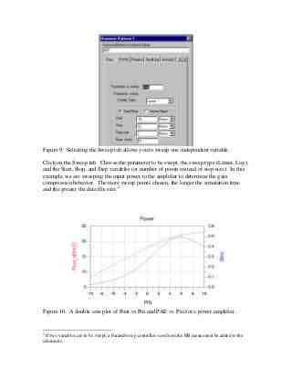
To perform an HB simulation, you only need to set one or more base frequencies and the sequence for each base frequency. In the context of high-frequency circuit simulation, HB offers several advantages for conventional time-domain transient analysis, where it allows frequency-domain voltage and current, directly calculating the steady-state spectral content of voltage or current in a circuit. The frequency integration required for temporary analysis is prohibitive in many practical cases.
Analog FastSPICE platform
The Siemens EDA Analog FastSPICE (AFS) platform is a simulation technology that provides superior nm-accurate circuit simulation, mixed signal simulation, and full-spectrum device sound analysis. AFS is a certified foundry by the world’s leading foundries delivering SPICE accuracy. It supports industry standard netlist syntax and is seamlessly integrated into the industry EDA design environment. The RF engine at AFS supports the Newton Shooting and Harmonic Balance methods with the latest innovations. For silicon-accurate characterization, the AFS platform includes a comprehensive full spectrum device noise analysis and integrates with Solido Variation Designer to deliver full coverage of variation-aware designs in the least order-of-magnitude simulation, but with brute force technique accuracy.
The recently announced FastSPICE eXTreme Analog Technology (AFS XT) improves performance for large post-layout netlists. There are no additional charges for existing and new customers. AFS XT can handle more than 300 million temporary capacity elements and deliver mixed signal simulations with the Symphony Mixed-Signal platform.
RF Harmonic Balance offerings
The AFS Harmonic Balance suite consists of HB analysis of large signals and AC small signals, transfer functions, noise, stability, and scatter parameter analysis. While single tone is supported for driven circuits and autonomous circuits, multi-tone is supported for driven circuits. This is most applicable for circuits with high dynamic range, for linear and moderately non-linear circuits and for circuits with distributed elements.
AFS HB solvers are further optimized for performance and convergence via automated intelligence algorithms. AFS HB uses multi-threaded capabilities for additional performance speedup versus single core operation. The parallel multi-core AFS (MCP) feature speeds up these simulations by 3.5x to 7x by efficiently using multi-core shared memory engines for Monte Carlo, sweeping, and angle simulations.
Table 1 below summarizes the AFS RF Harmonic Balance offerings.
table 1: AFS Harmonic Balance analysis.
HB analysis of large signals determines the periodic time varying operating point for a single tone, and the quasi-periodic time varying operating point for multi tone. All signals must be co-periodic with the base frequency. After a periodic steady-state solution is found, analysis of the listed small signals can be performed.
Capacity, performance and memory for RF HB analyses
Achieving true convergence in HB can be a challenge for complex designs. Convergence parameter relaxation is a logical approach, but it takes a toll on accuracy. Furthermore, the verification complexity increases with increasing harmonics. The extracted netlists introduce more complexity of convergence compared to schemas. Capacity refers to the number of elements contained in the netlist including active and passive devices, parasitic elements, etc. As shown in Figure 2, AFS RF analyzer can easily handle designs with high element count. The ability to handle large netlists is very important for RF analysis, especially when we are heading to an advanced process point.
Figure 2: example of AFS RF HB capacity.
Finally, faster simulations without loss of accuracy are needed to meet aggressive design time limits. Figure 3 shows an example of the runtime and memory utilization useful AFS XT from AFS for a variety of circuits.
Fig. 3: Comparison of AFS versus AFS XT (values greater than 1.0 indicate speed up with AFS XT and less memory utilization with AFS XT).
Summary
For driven and autonomous periodic circuits, choose your analysis machine wisely with the capabilities and benefits provided by AFS RF machines with Shooting Newton and Harmonic Balance. The Siemens EDA FastSPICE Analog platform offers a Harmonic Balance engine for single and multi-tone analysis and provides enhanced performance with superior convergence without compromising accuracy. The Harmonic Balance suite contains large HB signal analysis and a variety of small signal analysis. Take advantage of AFS RF HB’s multi-threaded capabilities for additional speed for designs that require gestures, angles, and statistical analysis.
Scott Guyton is director, solutions architecture at Siemens EDA.
What is tank configuration?
The standard tank configuration is a useful reference standard for mixing process design. They provide an adequate mix for most of the processing requirements that exist in the industry.
What is a mix tank? A mixing tank is a machine container that is used to mix several components. Tanks are made of different materials such as plastic, strong rubber, glass, but the most common of the Mixed Tanks are made of stainless steel.
What is tank baffle?
Baffles are long, flat plates that attach to the inside of the tank to prevent swirling and promote the movement of fluid up and down.
What is the purpose of the baffles?
Baffles are vanes — directing or obstructing or panels used to direct the flow of liquids or gases. It works on some household stoves and on some industrial process vessels (tanks), such as shell and tube heat exchangers, chemical reactors, and static mixers.
What is the purpose of baffle plates in a fuel tank?
A baffle plate is provided on the fuel tank to prevent fuel surge caused by vehicle tilting or sudden turning of the vehicle. In this case, fuel can be supplied stably to the fuel pump and the noise caused by the fuel surge can be reduced.
How do you size a mixing tank?
For most mixing applications, the ideal liquid level ratio for a tank diameter is 0.8, however, a ratio that is close to 1 to 1 is sufficient. The ratio is too small not to allow the correct axial mixing in the tank. Anything less than a ratio of 0.6 should be avoided.
How do you calculate the power of a mixer?
Power = Np * n3 * d5 * sg * K The numerical value of dimensionless power (Np) depends on several factors including impeller design, number of impeller and location in the tank, baffling tank and fluid viscosity. Typically the amount of power shown to interfere in a full turbulent flow.
What should be the distance of impeller from the bottom of the tank?
The normal C/T range is between 0.1 – 0.4. The bottom clearance can also be determined by the diameter of the impeller. For high shear mixes, 1 D out the bottom is optimal. For low speed agitation, clearance may be as low as ½ D.
How do tank baffles work?
How Do Baffles Work? Baffles work by disrupting the flow pattern and providing top -down flow. When mixing solid suspensions in a large cylinder tank, you will usually have a curved flow pattern regardless of the type of impeller you use.
How do you make baffles in a tank?
Why baffle plates are provided in fuel tank?
A baffle plate is provided on the fuel tank to prevent fuel surge caused by vehicle tilting or sudden turning of the vehicle. In this case, fuel can be supplied stably to the fuel pump and the noise caused by the fuel surge can be reduced.
Can a harmonic balancer leak oil?
Crankshaft oil leaks are more common in the front of your motor because the harmonic balance does not protect the oil seal and the larger flywheel and the front of the motor is usually subject to various road dust, salt, and grit that can deteriorate the seal over time.
What problems can be caused by poor harmonic balance? If the harmonic balancer becomes too old or fails and can no longer properly absorb harmonic vibration, the machine will shake too much. The shake will be even more readable, and therefore dangerous for machines at high speeds.
How do I know if my harmonic balancer is bad?
The most common symptoms of poor harmonic balance are:
- Vibration Machine. The harmonic job is to reduce the vibration applied to the crankshaft. …
- Noticeable Harmonic Balancer Wobble. …
- Noises are strange. …
- Illuminated Check Engine Lights. …
- Visible Wear or Damage.
How long does harmonic balancer last?
On certain machines, sometimes this is forever, as long as the life of the machine. With certain machines they can only last 50,000 miles or less in 10 years.
Can you drive a car with a bad harmonic balancer?
It is okay to drive with a bad harmonic balance. The bounce crankshaft will wear on the main direction. They can also tighten drive belts and possibly destroy danger to people and property.
What happens if you drive without a harmonic balancer?
In the absence of a balancer, unwanted vibration from the crankshaft can cause engine failure, such as used rod bearings and damaged crankshafts. A faulty balancer can also damage engine accessories, such as belts and engine-driven gears.
Is a harmonic balancer necessary?
The function of the harmonic balancer is to reduce the peak amplitude of torsional vibration to an acceptable level. Most OEM harmonic dampers are not designed to address the rpm and BHP levels experienced in the competition. That’s why drivers should consider high-performance dampers that fit the purpose.
Can you drive with a broken harmonic balancer?
It is okay to drive with a bad harmonic balance. The bounce crankshaft will wear on the main direction. They can also tighten drive belts and possibly destroy danger to people and property.
What seal is behind the harmonic balancer?
The crankshaft seal is installed behind the main crankshaft pulley of the engine, to serve it the need to remove the belt and crankshaft pulley and harmonic balance before it can be accessed.
What is harmonic balance simulation in cadence?
Harmonic balance works in the frequency domain and is an efficient way to describe an operating system in a steady state. HB is very efficient for systems that have sinusoidal tones. … Choosing a QPSS with a Harmonic Balance engine or choosing just the HB button will do the same thing.
What is a harmonic balance simulation? Harmonic balance simulation allows simulation of multi-tone circuits that indicate inter-modulation frequency conversion. This includes the conversion of frequencies between harmonics. Not only can the circuit itself produce harmonics, but each signal source (stimulus) can also produce harmonics or small signal sidebands.
What is PSS simulation cadence?
Periodic Stadium Analysis (PSS Analysis) calculates the periodic steady state response of a circuit at a given base frequency, with the simulation time not depending on the circuit time constant. … PSS analysis works with both autonomous and driven circuits.
Is Cadence Virtuoso an EDA tool?
The workshop included training sessions on Cadence design and simulation tools (Encounter, RTL Compiler, Virtuoso, Specter, Assura and Incisive). Cadence is a major provider of EDA and IP semiconductors. Our custom/analog tools help engineers design transistors, standard cells, and IP blocks that build SoCs.
What is virtuoso in cadence?
The Cadence® Virtuoso® System Design Platform is a holistic system-based solution that provides the functionality to run simulations and IC layouts with a single LVS-clean package of schematics. There are two key streams: implementation and analysis.
How do you do PSS analysis in Cadence?
How do you do simulation in cadence?
- Start Analog Environment (ADE L) â € ¢ With the extracted view open, in the Edit Virtuoso Layout window select Launch => …
- Analog simulator setup. â € ¢ …
- Set the Analog Environment to use Extracted View. …
- Set the stimulus file. …
- Setup Model File: …
- Setup Analysis. …
- Setup trace output. …
- Run the Simulation.
How do you open virtuoso cadence?
Launch Virtuoso Or, right click on the desktop and start the terminal. Then type: Page 3 3 Last update: 9/17/2017> cd ~> cadence load module> cadence_freepdk45 In a flash you should see a Cadence splash screen and the Virtuoso command window should appear: Open the Tools menu â € ¦
How does PSS simulation work?
PSS simulations show the voltage spectrum in different harmonics exhibited by this mixer test bench. PAC analysis provides information about the conversion gain with respect to the IF frequency. QPSS analysis was used to calculate the power conversion gain of power at the IF and RF frequencies.
What is PSS Pnoise?
PSS PNOISE is completely free of mortal noise. PSS PNOISE would be a more efficient way to simulate noise in a periodic circuit – and seem more accurate – unless the circuit has a large signal response to noise.
What is PSS simulation in cadence?
Periodic Stadium Analysis (PSS Analysis) calculates the periodic steady state response of a circuit at a given base frequency, with the simulation time not depending on the circuit time constant.
How do you calculate mixer?
MIXED FORMULA
- D = Blade diameter.
- H = Blade height.
- N = Number of slices.
- RPM = Revolutions Per Minute (shaft speed)
- 231 = Cubic inches per gallon.
- V1 = Volume lost per revolution.
- V2 = Volume moved per minute.
- G = Gallons moved per minute.
How do you calculate the intervention time? Typically, the mixing time is correlated with specific power inputs and geometrical parameters, like vessel diameter, H / D ratio, d / D ratio etc. with the following form: tm ~ (P / V) ^ -1 / 3*D ^ 2 /3*(d/D)^-1/3.
How do you calculate the speed of a mixer?
To calculate the tip speed you simply multiply the impeller diameter by pi (3.14159) which gives you the impeller circumference at the outermost end. You then multiply by the impeller rotational speed (usually rpm, or rps) and the result is tip speed.
How do you calculate blade rpm?
High speed dispersion blades generally need to run at a tip speed of 2,500 to 5,000 feet per minute. Your exact tip rate can be determined by using this equation: FPM = RPM x. 262 x Edge diameter (inches).
How do you calculate the power of a mixer?
Power = Np * n3 * d5 * sg * K The numerical value of dimensionless power (Np) depends on several factors including impeller design, number of impeller and location in the tank, baffling tank and fluid viscosity. Typically the amount of power shown to interfere in a full turbulent flow.
How do you calculate mixing?
HOW TO CALCULATE THE PERCENTAGE WHEN THE MIX RATIO KNOWS. Divide 1 by the total number of parts (aqueous solution). For example, if the ratio of your mixture is 8: 1 or 8 parts water to 1 part solution, there are (8 1) or 9 parts. The percentage of mixture is 11.1% (1 divided by 9).
How do you calculate water mixing ratio?
The ratio of water vapor mixture is not a unit, but often we put in kgâ € “1 g. The ratio of water vapor mixture, w, is usually at most about 40 g kgâ € “1 or 0.04 kg kgâ €“ 1, so even for this much water vapor, q = 0.040/(1 0.040) = 0.038 or 38 g kgâ € “1.
How are paint mixing ratios calculated?
Paint Ratio Formula To calculate the paint ratio, divide the number of base parts by the number of thinner parts.
Can a harmonic balancer cause a misfire?
The harmonic balancer also acts as a pulley for your vehicle’s drive belt so that when it first fails, your engine belt can slip, operate noisily or be damaged. You can experience this as an inability to accelerate efficiently, dips in fuel economy and engine misfiring or backfiring.
Does harmonic balance affect time? Another symptom of a potential problem with harmonic balance is, the time sign is wrong. If the layers separate or slip, the timing mark may move. This will make it, difficult if not impossible; to correct engine time and timing lights.
Can a car run with a bad harmonic balancer?
Can you drive a car with a broken harmonic balance? If you have a poor harmonic balance, you should not drive. It is inevitable that the crankshaft will bounce on the bearings. In addition, it can tighten drive belts and possibly cause them to fall, causing danger to people.
Will a car start with a bad harmonic balancer?
According to the AA1 Car automotive diagnostic web page, poor ignition time is caused by irregular signals from the camshaft sensor caused by the inability of harmonic balance to balance the components. This situation causes your vehicle to be unable to start.
How do you test for a bad harmonic balancer?
Start your engine and check the harmonic balancer to see if it wobbles while the engine is running. Pick up the flashlight and light it directly into the balancer to see if it goes in and out while rotating. When shaking, the harmonic balance is poor.
Can you start a car without a harmonic balancer?
Can You Start a Car Without a Harmonic Balancer? There will be no air conditioning, no power steering, no alternator, and no water pump without belts that go around the crankshaft pulley. Without it, the engine bearings can be damaged. This needs to be replaced.
Why poor harmonic balance can cause engine failure? Although the harmonic balancer seems simple enough, if it fails, it can cause major problems. Without the balancer dampening unwanted crankshaft vibration, engine failures, such as used rod bearings and a damaged crankshaft, can result. A faulty balancer can damage belts and engine-driven accessories as well.
Can you drive with a broken harmonic balancer?
It is okay to drive with a bad harmonic balance. The bounce crankshaft will wear on the main direction. They can also tighten drive belts and possibly destroy danger to people and property.
How much does it cost to fix a harmonic balancer?
How much does a harmonic balancer usually cost? Harmonic balancer replacements can be as little as $ 150 to as much as $ 550.
Is it bad to drive on a bad harmonic balancer?
A faulty balancer can damage belts and engine-driven accessories as well. It is also possible for the balancer to fly separately, resulting in damage to various underhood components. Without a doubt, you should immediately replace the wrong harmonic balance.
Is a harmonic balancer necessary?
The function of the harmonic balancer is to reduce the peak amplitude of torsional vibration to an acceptable level. Most OEM harmonic dampers are not designed to address the rpm and BHP levels experienced in the competition. That’s why drivers should consider high-performance dampers that fit the purpose.
Does harmonic balancer affect performance?
A harmonic balancer is designed to keep the crankshaft torsional vibrations at check that occur when the engine is running. So, no matter what type of changes you make to the engine, adding more horsepower will change its harmonics.
Do I need a new harmonic balancer?
Harmonic balancers have many names, such as damper, crankshaft pulley and crankshaft balancer, among them. While these parts may not be worn, or known to wear, as quickly as a traditional idler pulley or belt tensioner, balancers actually wear and eventually need to be replaced.
Will a car start with a bad harmonic balancer?
According to the AA1 Car automotive diagnostic web page, poor ignition time is caused by irregular signals from the camshaft sensor caused by the inability of harmonic balance to balance the components. This situation causes your vehicle to be unable to start.
How do I know if my harmonic balancer has slipped?
There is a clerk’s mark on the surface of the balancer you can see while it is installed. The mark is chiseled across between the center hub and the outer ring. Rotate the machine with a 3/4 wrench and look closely for marks. If the mark on the hub does not match the mark on the ring then insert.
Can I drive my car with a bad harmonic balancer?
A faulty balancer can damage belts and engine-driven accessories as well. It is also possible for the balancer to fly separately, resulting in damage to various underhood components. Without a doubt, you should immediately replace the wrong harmonic balance.
