


Wireless channel fading is the rapid variation in received signal strength caused by multipath, and its impact on OFDM systems is that each subcarrier sees its own random gain and phase. OFDM turns a frequency-selective channel into many flat ones, but faded subcarriers still lose data, and fast time variation adds inter-carrier interference. Channel coding, pilots and diversity are what keep the link working.
This article covers the fading side of OFDM performance. The basic waveform is described in the OFDM overview, and wider propagation in antennas and propagation for radio design.
Wireless channel fading: what causes it
Radio waves reach a receiver by several paths, reflected and scattered by buildings, terrain and vehicles. Each path arrives with its own delay and phase, and the paths add as phasors. They can reinforce or cancel, so moving a fraction of a wavelength can change the level by tens of decibels. Fading is usually split into two parts:
- Large-scale fading comes from path loss and shadowing, and changes over many wavelengths.
- Small-scale fading comes from multipath interference, and changes over about a wavelength or across a modest bandwidth.
With many scattered paths and none dominant, the channel gain is a complex Gaussian variable, so the envelope is Rayleigh distributed and the power is exponential. A strong line-of-sight path gives a Rician channel instead, with shallower fades.
Frequency-selective fading and coherence bandwidth
Delay spread measures how far multipath echoes are spread in time, and it sets how the channel changes with frequency. Coherence bandwidth is the frequency span over which the response stays roughly constant. A common estimate, for correlation of about 0.5, is:
Bc ≈ 1 / (5στ)
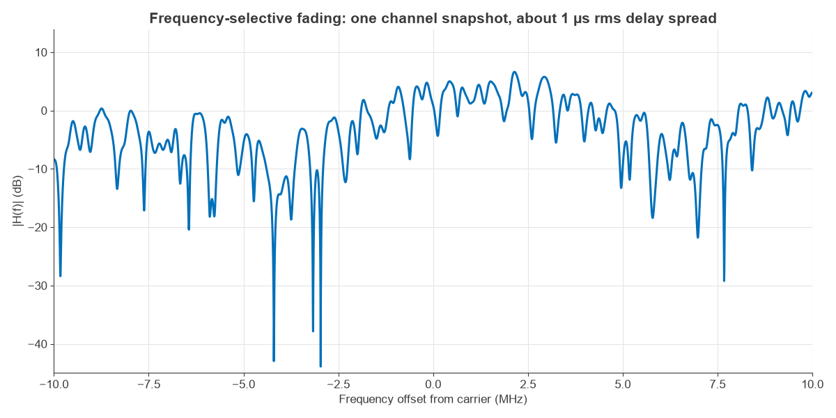
where στ is the rms delay spread. Figure 1 shows a simulated channel with about 1 µs of delay spread. Across 20 MHz there are many nulls, some deeper than 30 dB. A single-carrier signal would need an equalizer to deal with these, as compared in single-carrier and multi-carrier modulation.
Time-selective fading, Doppler and coherence time
Movement shifts each path by up to the maximum Doppler frequency:
fd = v fc / c
Paths from different directions shift differently, so the channel varies in time. Coherence time gives the interval over which the channel is roughly stable. A common estimate is Tc ≈ 0.423 / fd. Fast fading and slow fading are defined by comparing this with the symbol or frame duration, not by speed alone.
Fading parameters: a worked OFDM example
Consider a 5G NR style link at 3.5 GHz with 30 kHz spacing, 1 µs rms delay spread, and a terminal moving at 120 km/h.
- Coherence bandwidth: Bc ≈ 1 / (5 × 1 µs) = 200 kHz, or about 6.7 subcarriers. Each 30 kHz subcarrier therefore sees nearly flat fading, while the whole carrier is strongly frequency selective.
- Doppler: v = 33.3 m/s, so fd = 33.3 × 3.5 × 109 / (3 × 10⁸) = 389 Hz.
- Coherence time: Tc ≈ 0.423 / 389 = 1.09 ms, about two 0.5 ms slots.
- Useful symbol time: T = 1 / 30 kHz = 33.3 µs, so the channel barely changes over one symbol.
Impact of fading on OFDM performance
Fading on each subcarrier
After the FFT, each subcarrier output is Yk = Hk Xk + Nk. A one-tap equalizer divides by Hk, which corrects phase and amplitude, but it also scales the noise. A subcarrier in a null has poor SNR, and no equalizer can restore it.
Figure 2 shows the result for uncoded QPSK. In AWGN, an Eb/N0 of 10 dB gives a bit error rate near 3.9 × 10⁻⁶. Under Rayleigh fading with the same average SNR, the rate is about 0.023, because the errors come from subcarriers in deep fades. The formula is Pb = ½[1 − √(γ / (1 + γ))], so each tenfold improvement in error rate requires about 10 dB more SNR: 0.0025 at 20 dB and 2.5 × 10⁻⁴ at 30 dB.
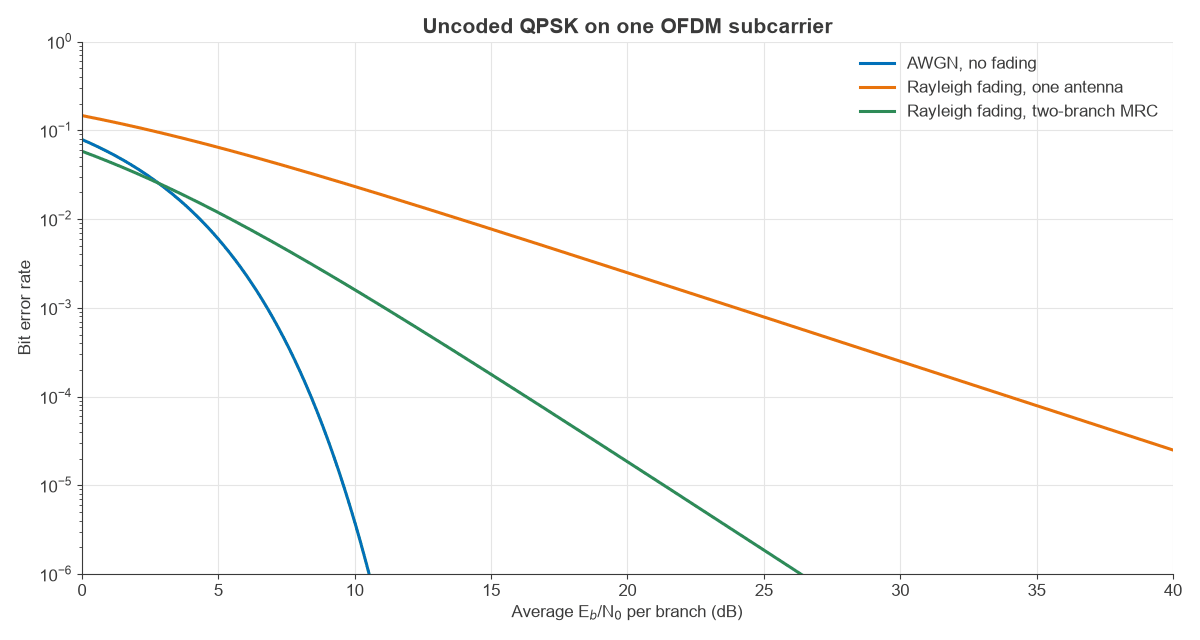
The exponential power distribution also sizes the fade margin. With a mean SNR of 10 dB, the fraction of subcarriers below 0 dB is 1 − e−0.1 = 9.5%. Keeping an unprotected link in outage for only 1% of the time takes a margin of about 20 dB.
Delay spread and the cyclic prefix
The cyclic prefix absorbs echoes shorter than its length. Energy arriving later causes inter-symbol and inter-carrier interference. A rough estimate for an exponential delay profile is that the energy outside the prefix is e−Tcp/στ. For 1 µs delay spread, the 2.3 µs prefix at 30 kHz leaves about 10% of the energy outside, which limits SINR to around 10 dB in this crude estimate. The 4.7 µs prefix at 15 kHz leaves about 0.9%, or a limit near 20 dB. That is why a heavily dispersive macro cell favours narrower spacing, and why the choice of numerology balances delay spread against Doppler. Real links are often better than this because timing is set to capture the strongest energy.
Doppler and inter-carrier interference
If the channel changes during a symbol, the subcarriers are no longer orthogonal, and each one leaks into its neighbours. A commonly used upper limit on the interference power, relative to the signal, is (π fd T)2 / 3. For the worked example, fdT = 0.013, which gives a signal-to-interference ratio of at least 32.6 dB. This is fine for most modulation, though it limits 256-QAM at high SNR.
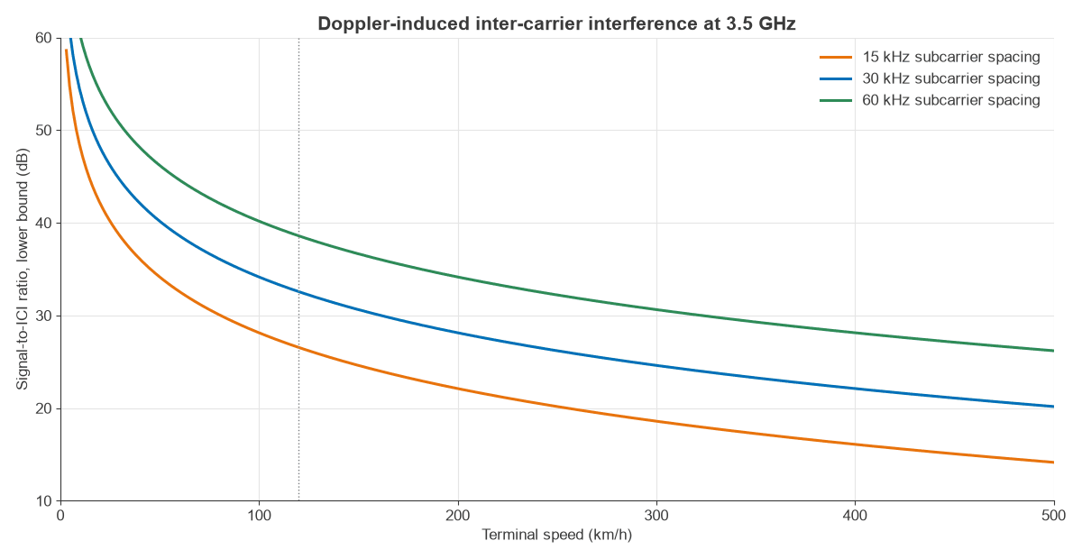
Figure 3 shows the trend. At 120 km/h the bound is 26.5 dB for 15 kHz spacing and 38.6 dB for 60 kHz. At 500 km/h with 30 kHz spacing it falls to 20.2 dB. Phase noise produces similar leakage, so the two effects should be budgeted together.
Channel estimation in OFDM fading channels
Coherent detection needs an estimate of Hk, so known pilot symbols are placed in the time-frequency grid. The least-squares (LS) estimate at a pilot is simply Ĥk = Yk / Xk. It requires no channel statistics, but it keeps the full noise of the measurement. Minimum mean square error (MMSE) estimation uses the channel correlation to reduce noise, at the cost of more computation.
Pilot density follows the same two coherence figures, since the pilots must sample the channel fast enough in both dimensions:
- In frequency, spacing must be below about 1 / (2τmax). For 5 µs maximum delay, that is 100 kHz, or about three subcarriers at 30 kHz.
- In time, spacing must be below about 1 / (2fd). For 389 Hz, that is 1.28 ms, and practical designs oversample this limit.
Channel estimates are also the source of the feedback described in channel state information.
Mitigating fading in OFDM systems
- Coding and interleaving spread each code block across subcarriers, so a fade removes a few symbols that the decoder can rebuild. This frequency diversity is why coded OFDM performs far better than Figure 2 suggests.
- Antenna diversity combines signals that fade independently. Figure 2 shows that two-branch maximal ratio combining steepens the slope, as explained in diversity techniques.
- Link adaptation chooses modulation and coding to suit the measured channel, and a scheduler can assign each user its strongest resource blocks.
- Hybrid ARQ retransmits failed blocks, usually at a time when the channel has changed.
Frequently asked questions
What is the difference between fast and slow fading?
Fast fading has a coherence time shorter than the symbol or block duration, so the channel varies within it. Slow fading has a coherence time longer than that, so the channel stays roughly fixed. The speed alone does not decide it, because symbol duration matters as well.
Why is OFDM resistant to frequency-selective fading?
Each subcarrier is much narrower than the coherence bandwidth, so it sees a roughly flat channel that a single complex gain can correct. The cyclic prefix prevents echoes from causing interference between symbols.
How does Doppler affect OFDM?
Doppler makes the channel vary during a symbol, which breaks orthogonality and causes inter-carrier interference. It also means the pilots must be repeated often enough to track the channel. Wider subcarrier spacing reduces the interference.
How is the channel estimated in OFDM?
Known pilots are sent on selected subcarriers and symbols. The receiver forms an LS or MMSE estimate at those points and interpolates across time and frequency.
Related topics
Background is available in the RF fundamentals section, and spatial multiplexing in 5G networks shows how NR uses the same multipath to carry extra layers.