
Orthogonal frequency division multiplexing (OFDM) splits a high-rate data stream across many closely spaced, mutually orthogonal subcarriers, each carrying a slow QPSK or QAM symbol. Because each symbol is long compared with the channel’s delay spread, a cyclic prefix can absorb multipath and a one-tap equalizer can correct each subcarrier. The price is a high peak-to-average power ratio and sensitivity to frequency offset and phase noise.
OFDM is the waveform behind Wi-Fi, LTE, 5G NR, and digital TV and radio broadcasting. It builds on the single-carrier digital modulation techniques, and this page covers how it works, its numbers, and its effect on RF hardware.
OFDM Principle: Why Many Slow Subcarriers
A wideband single-carrier signal has short symbols. If the channel has echoes lasting longer than a symbol, each one smears across several others, and the receiver needs a long, complex equalizer. OFDM divides the same data among N subcarriers, so each symbol lasts N times as long. An echo of a few hundred nanoseconds then spoils only a small fraction of a 3.2 μs or 66.7 μs symbol.
Orthogonal subcarriers
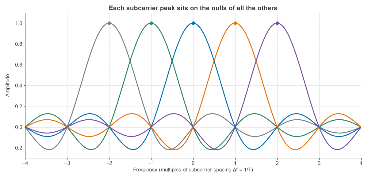
Subcarriers are spaced at exactly Δf = 1/T, where T is the useful symbol time. A rectangular symbol of length T has a sinc spectrum with nulls every 1/T, so each subcarrier’s peak falls on the nulls of all the others. Spectra overlap, yet they do not interfere, since the integral of any two different subcarriers over T is zero.
The OFDM Transmitter and Receiver
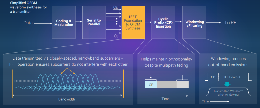
The inverse FFT does the multicarrier modulation in a single operation, so no bank of oscillators is needed.
- Coded bits are mapped to PSK or QAM symbols, with pilots on known subcarriers.
- An IFFT turns one block of N frequency-domain symbols into N time samples.
- A cyclic prefix is copied from the end of the block to the front.
- DACs and an IQ modulator move the signal to RF.
- The receiver reverses the chain: it synchronises, drops the prefix, runs an FFT, and divides each subcarrier by its channel estimate.
Edge subcarriers and the DC subcarrier are usually left empty. These guard bands let filters roll off, and they help to meet the spectral mask and ACLR limits.
Cyclic Prefix and Multipath
The cyclic prefix makes the channel look circular over the FFT window. Provided the delay spread is shorter than the prefix, each subcarrier simply gets multiplied by one complex number, H(fk), and a one-tap equalizer divides it out. Beyond that, energy from the previous symbol leaks into the window and orthogonality breaks.
A simulation confirms this directly. Using a 64-point FFT with 52 active subcarriers at 20 MHz sampling, an 800 ns prefix (16 samples) and 16-QAM, a single echo at −6 dB was added.
| Echo delay | Relative to prefix | Equalized EVM |
|---|---|---|
| 500 ns | Inside | About 3 × 10⁻¹⁴ %, effectively zero |
| 1000 ns | 200 ns beyond | 19.3% |
The result is sharp. Inside the prefix the echo is fully removed, apart from numerical rounding. A further 500 ns gives an EVM of 19.3%, far worse than a 16-QAM link can tolerate, which is why the prefix is sized to the expected channel. The remaining caveat is that frequency-selective fading still leaves some subcarriers weak, so OFDM relies on error correction coding and interleaving to recover the bits lost on them.
Worked Example: A 20 MHz OFDM Symbol
The classic 20 MHz Wi-Fi OFDM numerology, from 802.11a/g, makes a good example, using these figures as approximate design values.
- FFT size N = 64 at 20 MHz sampling, so Δf = 20 MHz / 64 = 312.5 kHz.
- Useful symbol time T = 1/Δf = 3.2 μs.
- Cyclic prefix 0.8 μs, for a total symbol time of 4.0 μs.
- Prefix energy cost: 10log10(4.0/3.2) = 0.97 dB.
- A 0.8 μs delay matches a path difference of 240 m.
- 52 used subcarriers, 48 for data and 4 for pilots, occupy about 52 × 312.5 kHz = 16.25 MHz.
With 64-QAM at code rate 3/4, the rates are:
- Coded bits per symbol: 48 × 6 = 288, a gross rate of 288 / 4 μs = 72 Mbit/s.
- User rate: 72 × 3/4 = 54 Mbit/s, or 2.7 bit/s/Hz in the 20 MHz channel.
In AWGN, each subcarrier behaves like an independent QAM channel, so the BER curves from the QAM page apply, with the prefix loss added. For 64-QAM at an uncoded BER of 10−6, the requirement rises from 18.78 dB to about 19.75 dB of Eb/N0.
Numerology in cellular systems
LTE uses 15 kHz spacing, with a 66.67 μs useful symbol and a normal prefix of roughly 4.7 μs, an overhead of about 6.6% and a path allowance of about 1.4 km. 5G NR scales that spacing by powers of two:
| Subcarrier spacing (kHz) | Useful symbol (μs) | Typical use |
|---|---|---|
| 15 | 66.67 | Sub-6 GHz, wide coverage |
| 30 | 33.33 | Sub-6 GHz |
| 60 | 16.67 | Sub-6 GHz and mmWave |
| 120 | 8.33 | mmWave |
NR also defines 240 kHz, for synchronisation signals only, and Release 17 adds 480 and 960 kHz for the 52.6 to 71 GHz range. Wider spacing tolerates more phase noise and Doppler, which suits the mmWave bands, while the shorter prefix suits small cells. See the 5G RF front end article for the hardware side.
PAPR: The Cost for the Power Amplifier
With many subcarriers, the time signal is a sum of many independent phasors and tends toward a complex Gaussian waveform. Occasionally they align and the peak is far above average. For equal-power subcarriers the theoretical maximum is 10log10N, and 16-QAM corner points add up to 2.55 dB more, but that case is extremely rare; what matters is the probability curve.
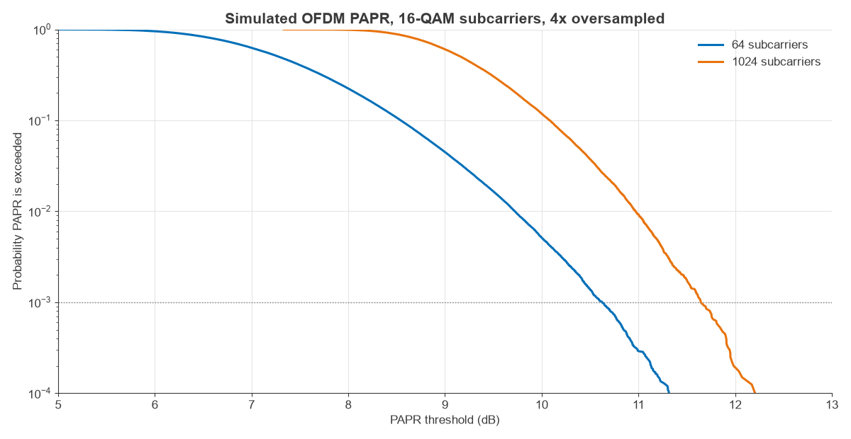
A 4× oversampled simulation of 16-QAM subcarriers gave the following PAPR thresholds.
| Subcarriers | Exceeded 10% of symbols (dB) | Exceeded 0.1% of symbols (dB) | 10log10N (dB) |
|---|---|---|---|
| 64 | 8.54 | 10.63 | 18.06 |
| 1024 | 10.08 | 11.65 | 30.10 |
Sixteen times as many subcarriers adds only about 1 dB at the 0.1% level. In practice a power amplifier must back off by several dB from P1dB, or the system applies crest factor reduction and digital predistortion. A compressed peak causes in-band EVM and out-of-band regrowth. Modulation, EVM and PAPR looks at this trade in detail. The uplink in LTE and some 5G modes uses DFT-spread OFDM, which lowers PAPR for battery-powered handsets.
OFDM Impairments: Frequency Offset, EVM and Phase Noise
Carrier frequency offset
A frequency offset of ε subcarrier spacings shifts the samples off the nulls and causes inter-carrier interference. With all subcarriers active, the resulting EVM is roughly πε/√3 for small ε.
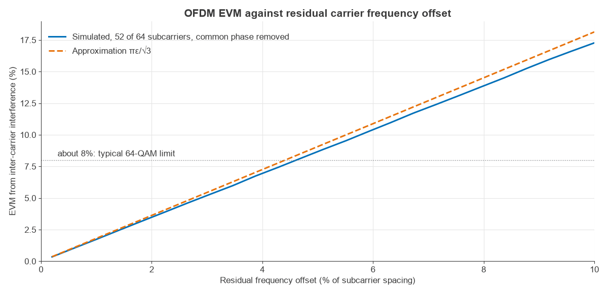
The simulation behind Figure 3 used 64-QAM, 52 of 64 subcarriers, and removed the common phase rotation, as a real receiver would using pilots. Results for the 312.5 kHz spacing:
| Residual offset ε | Offset (kHz) | Simulated EVM (%) | Approximation (%) | EVM (dB) |
|---|---|---|---|---|
| 1% | 3.125 | 1.73 | 1.81 | −35.2 |
| 2% | 6.25 | 3.48 | 3.63 | −29.2 |
| 5% | 15.625 | 8.68 | 9.07 | −21.2 |
An offset of 6.25 kHz at a 5.8 GHz carrier is about 1.08 ppm, the kind of error a low-cost crystal could easily make. Even with the common rotation tracked, its inter-carrier interference would take almost the whole of a 3.5% 256-QAM budget. Pilot-based correction removes nearly all of it, so the table describes the residual after synchronisation.
Phase noise
Phase noise has two effects in OFDM. The low-frequency part rotates all subcarriers together, a common phase error that pilots can track. The part beyond the subcarrier spacing acts like frequency offset and causes inter-carrier interference that cannot be tracked.
Frequently asked questions
Why is the cyclic prefix used in OFDM?
It keeps subcarriers orthogonal in multipath. Copying the end of the symbol to the front means an echo shorter than the prefix appears as a simple gain and phase change per subcarrier, which a one-tap equalizer removes. It costs energy and time, about 0.97 dB in the 802.11a/g example.
What are the main disadvantages of OFDM?
The main ones are a high peak-to-average power ratio, about 10 to 12 dB at the 0.1% level in the simulation above, and sensitivity to frequency offset and phase noise. Both raise the cost of the RF chain, and the prefix and pilots use up capacity.
How is OFDM different from FDM?
Classic frequency division multiplexing separates channels with guard bands and filters. OFDM overlaps subcarriers and relies on orthogonality, so it needs no guard between them, which gives much better spectral efficiency. An FFT replaces the bank of filters.
What is the difference between OFDM and OFDMA?
OFDM gives all subcarriers in a symbol to one user at a time. OFDMA assigns different groups of subcarriers to different users in the same symbol, which is the method used by LTE and 5G downlinks. The waveform and RF demands are largely the same.
Related topics
QAM and PSK are the constellations OFDM carries, and phase modulation explains the phase impairments. Digital modulation techniques gives the broader comparison. For the system view, see MIMO, beamforming and phased arrays and the RF link budget.