

MIMO configurations describe how many antennas a link uses and who shares them. The antenna count is written Nt×Nr, as in 2×2 or 4×4, and the deployment type is single-user MIMO, multi-user MIMO, massive MIMO or cooperative MIMO. Together they set the number of streams a system can carry and the hardware and channel knowledge it needs.
This article covers the notation and the four deployment types, with capacity numbers for each. The smallest cases, with one antenna at one end, are compared in SISO vs MIMO, and the three benefits of multiple antennas are explained in MIMO and multiple antenna systems.
How MIMO configurations are named
The basic notation counts antennas: T×R means T transmit and R receive antennas. Direction matters, so a phone with a 4×2 downlink has a 2×4 uplink if the same antennas are used in both directions, assuming it can transmit on both.
A common extension is T×R:S, where S is the number of spatial streams. A Wi-Fi radio labelled 3×3:2 has three transmit and three receive chains, and it supports two streams. The maximum for one link is always:
S ≤ min(Nt, Nr)
Antennas and RF chains are not always equal. A massive MIMO radio may list 64T64R, meaning 64 chains. A hybrid array can have many antenna elements behind fewer chains, and streams are limited by the chains. Element counts in product literature can therefore overstate what the signal processing can see.
Symmetric and asymmetric antenna configurations
The capacity of a link with no transmit CSI and equal power on each antenna is:
C = log2 det(I + (ρ/Nt)HHH) b/s/Hz
The table averages this over i.i.d. Rayleigh channels with 300,000 draws per entry. The last column shows the capacity at 20 dB with transmit CSI and water-filling, from 100,000 draws. Here ρ is total transmit power over noise at each receive antenna.
| Configuration | Max streams | Capacity at 10 dB | Capacity at 20 dB | At 20 dB with transmit CSI |
|---|---|---|---|---|
| 1×1 | 1 | 2.91 | 5.88 | 5.88 |
| 2×1 | 1 | 3.17 | 6.28 | 7.27 |
| 1×2 | 1 | 4.06 | 7.27 | 7.27 |
| 2×2 | 2 | 5.55 | 11.29 | 11.32 |
| 4×2 | 2 | 6.27 | 12.49 | 14.46 |
| 2×4 | 2 | 8.05 | 14.46 | 14.46 |
| 4×4 | 4 | 10.94 | 22.13 | 22.28 |
| 8×8 | 8 | 21.81 | 43.97 | 44.42 |
Capacities are in b/s/Hz. These results give practical rules:
- Symmetric links scale linearly. From 2×2 to 4×4 to 8×8, capacity at 20 dB goes 11.3, 22.1, 44.0. Each doubling of antennas at both ends doubles capacity.
- Adding antennas at one end adds SNR, not streams. Going from 2×2 to 2×4 adds 3.2 b/s/Hz at 20 dB. About 1.9 of that is the 3 dB of array gain, and the rest comes from better-conditioned streams. It does not double the rate.
- Extra receive antennas beat extra transmit antennas without CSI. A 2×4 link gets 14.5 and a 4×2 link gets 12.5, a gap of 2.0 b/s/Hz. With transmit CSI, the gap closes and both reach 14.5. The transmitter needs channel knowledge to focus its extra antennas.
- Transmit CSI adds little to symmetric links at high SNR. It adds 0.03 b/s/Hz on 2×2 at 20 dB. MIMO precoding is worth more at low SNR or where the antenna counts are unequal.
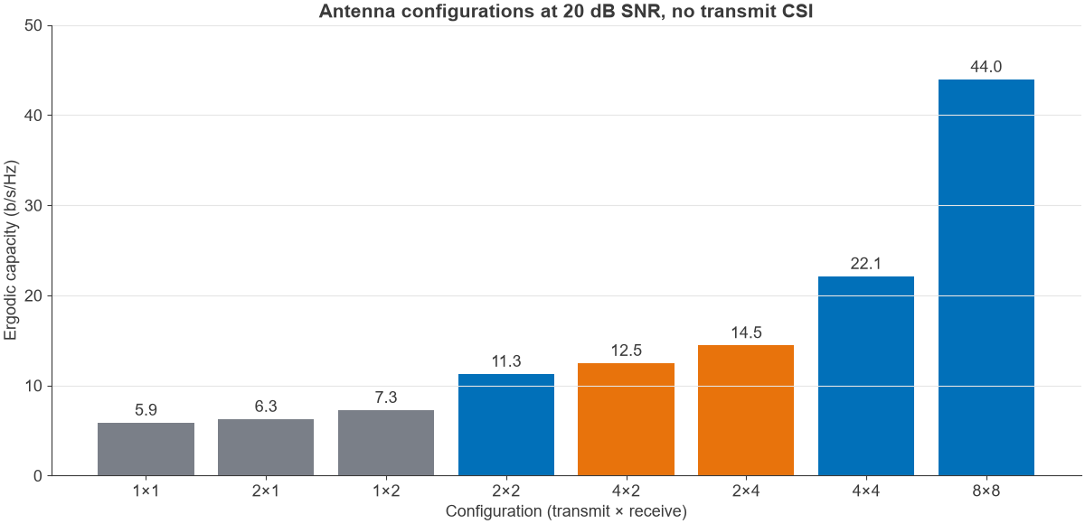
Real channels do less well than this table, since correlated antennas reduce the effective rank. The capacity of an i.i.d. channel should be read as a ceiling.
Single-user MIMO (SU-MIMO)
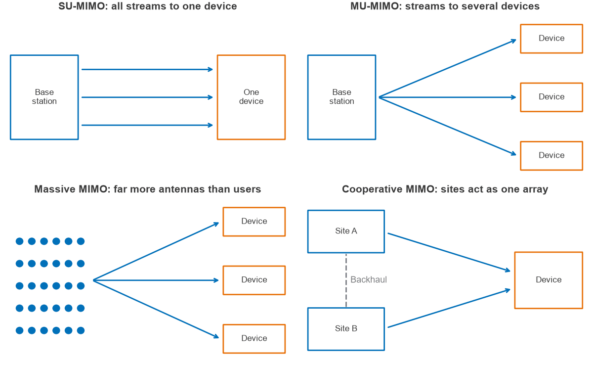
SU-MIMO sends all streams in one time and frequency resource to one device. It is the configuration behind the table above. Its limit is the receiver: a device has few antennas, so 2 to 4 layers is a typical ceiling in phones, and scaling further requires more antennas in a small space. Small spacing also raises correlation, which limits the value of further antennas.
Multi-user MIMO (MU-MIMO)
MU-MIMO serves several devices in the same resource by separating them in space. The base station needs enough antennas for its users, but each device can be simple, so capacity is no longer limited by the antennas on one device. The cost is that transmit CSI is essential, because the transmitter must null each user’s stream at the others.
Zero-forcing sum rate
With M transmit antennas and K single-antenna users in Rayleigh fading, a zero-forcing downlink gives each user an effective power gain with a Gamma(M-K+1, 1) distribution, and the power per user is ρ/K. The sum rate is:
R = K · E[log2(1 + (ρ/K)X)], X ~ Gamma(M – K + 1, 1)
The term M-K+1 shows the trade-off. Each user added takes one degree of freedom away from every user’s gain. Serving as many users as antennas is a poor choice, because the channel inverse then becomes badly conditioned.
Worked example: 4 transmit antennas at 10 dB
The table evaluates the formula with 1 million draws at ρ = 10 dB and at 20 dB.
| Antennas M | Users K | Sum rate at 10 dB | Sum rate at 20 dB |
|---|---|---|---|
| 4 | 1 | 5.2 | 8.5 |
| 4 | 2 | 7.6 | 14.0 |
| 4 | 3 | 8.0 | 17.1 |
| 4 | 4 | 6.0 | 16.1 |
Rates are in b/s/Hz. At 10 dB, serving three users gives 8.0 against 5.2 for one, which is a gain of about 55%. Serving a fourth user lowers the sum to 6.0. The best number of users is below M, and a scheduler should leave some spatial room unless SNR is very high. These figures assume perfect CSI, and in practice stale or quantised CSI leaves residual interference between users, which lowers them.
Massive MIMO
Massive MIMO is MU-MIMO with far more base station antennas than users, typically tens to hundreds of antennas at a site. Its advantage follows from the same formula. With M much larger than K, the term M-K+1 stays close to M, so every user gets large array gain and the channels of different users become close to orthogonal.
| Antennas M | Users K | Sum rate at 10 dB | Sum rate at 20 dB |
|---|---|---|---|
| 16 | 4 | 20.1 | 33.2 |
| 16 | 8 | 28.4 | 54.0 |
| 16 | 16 | 9.9 | 38.2 |
| 64 | 8 | 49.3 | 75.7 |
| 64 | 16 | 79.5 | 132.0 |
| 64 | 32 | 111.4 | 213.8 |
| 64 | 64 | 12.7 | 73.5 |
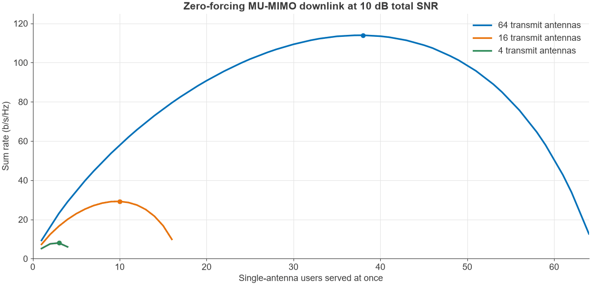
At 10 dB, 64 antennas peak at 114 b/s/Hz with 38 users, and 16 antennas peak at 29 b/s/Hz with 10 users. Both peak at about 60% of M. Fully loading either array collapses the rate, as Figure 3 shows.
These numbers come from ideal channels. Real arrays are limited by pilot contamination between cells, by calibration between uplink and downlink chains in time division duplex, and by the correlated nature of real channels. A sector array with 32 or 64 chains is a common mid-band arrangement. Massive MIMO for spectral efficiency and MIMO, beamforming and phased arrays cover it further.
Cooperative MIMO
Cooperative MIMO (Co-MIMO), also called network MIMO, coordinated multipoint or distributed MIMO, shares antennas across sites. Two or more base stations act as a single array serving a user, turning interference at a cell edge into signal. The antennas are far apart, so their paths decorrelate easily and they see different shadowing, which adds macro diversity.
The cost is in the backhaul. Sites must share CSI, and joint transmission needs data at every site, with timing and phase aligned. Coherent operation also demands tight oscillator synchronisation. Lighter forms of coordination share only scheduling or beam choices, giving less gain for far less backhaul.
Comparing the MIMO configurations
| Type | Serves | Key limit | Transmit CSI | Typical setting |
|---|---|---|---|---|
| SU-MIMO | One device, several streams | Antennas on the device | Helpful | Wi-Fi, phones in good SNR |
| MU-MIMO | Several devices in one resource | Base antennas and CSI quality | Essential | Wi-Fi access points, LTE and 5G cells |
| Massive MIMO | Many devices, M much larger than K | Pilots and calibration | Essential | Mid-band 5G macro sites |
| Cooperative MIMO | One or more devices from several sites | Backhaul and synchronisation | Essential for joint transmission | Dense networks, cell edges |
Standards differ on the maxima. As a rough guide, Wi-Fi specifications allow up to about 8 streams for an access point, while client devices usually have 2. Cellular specifications allow several layers per device, with 4 typical in mid-band phones and 2 typical at millimetre wave. Check the current release for exact limits.
Choosing a MIMO configuration
Start from the traffic and the devices. If one high-rate device dominates, as in point-to-point backhaul, SU-MIMO is the natural choice, and the design effort goes into antenna separation. If many devices share a site, added base antennas give more benefit through MU-MIMO than through more streams per device. If interference at cell edges dominates, coordination across sites may be worth more than extra antennas on one site.
Hardware is the other constraint. Each extra chain adds an ADC or DAC, mixer, filtering and power, so chain count grows cost roughly in proportion. Noise figure and phase noise budgets also tighten with streams. Radio architectures and RF design describe those trade-offs.
Frequently asked questions
What does 4×4 MIMO mean?
It means four transmit and four receive antennas on a link, supporting up to four spatial streams. In i.i.d. Rayleigh fading at 20 dB, its capacity is about 22 b/s/Hz, against about 6 b/s/Hz for a single antenna at each end. Real channels yield less.
What is the difference between SU-MIMO and MU-MIMO?
SU-MIMO sends all streams to one device at once. MU-MIMO sends streams to several devices in the same time and frequency resource, separated in space. MU-MIMO needs accurate transmit CSI and raises total cell capacity more than the rate of any one device.
Is 4×2 the same as 2×4?
Not without transmit CSI. At 20 dB, a 2×4 link has about 14.5 b/s/Hz and a 4×2 link about 12.5 b/s/Hz. With full transmit CSI they are equal, since capacity depends on the same singular values of the channel.
How many users should a massive MIMO base station serve?
For a zero-forcing downlink in ideal Rayleigh fading at 10 dB, the sum rate peaks with users at about 60% of the antenna count. In practice, pilot overhead and CSI quality usually push the best number lower.
Related topics
Spatial multiplexing explains how streams are separated, and spatial diversity and spatial multiplexing covers how a link trades reliability for rate. Beamforming and channel state information describe what the transmitter needs to serve several users.