


Impedance matching techniques differ between transmitting and receiving systems because the two ends optimize different things. A transmitter match presents the load line that gives the power amplifier its output power and efficiency, while a receiver match presents the source impedance that gives the low-noise amplifier its lowest noise figure. Neither is usually a conjugate match, so the same antenna port often needs two different networks.
This article is about that split. For the general idea, the mismatch formulas and an L-network walk-through, start with what impedance matching is and why it matters. Here the focus is what changes when the network sits behind a power amplifier or in front of an LNA.
Impedance matching in transmit and receive chains
| Design question | Transmit side | Receive side |
|---|---|---|
| Device being matched | Power amplifier output | LNA input |
| Target impedance | Load line Ropt or load-pull contour | Noise match Γopt |
| Main penalty for network loss | Heat and lost output power | Direct addition to noise figure |
| Limiting stress | Voltage, current, reflected power | Blocker level, overload |
| Typical topology | Low-pass L or multi-section network with harmonic control | Single L section with high-Q parts |
RF matching networks for the transmitter
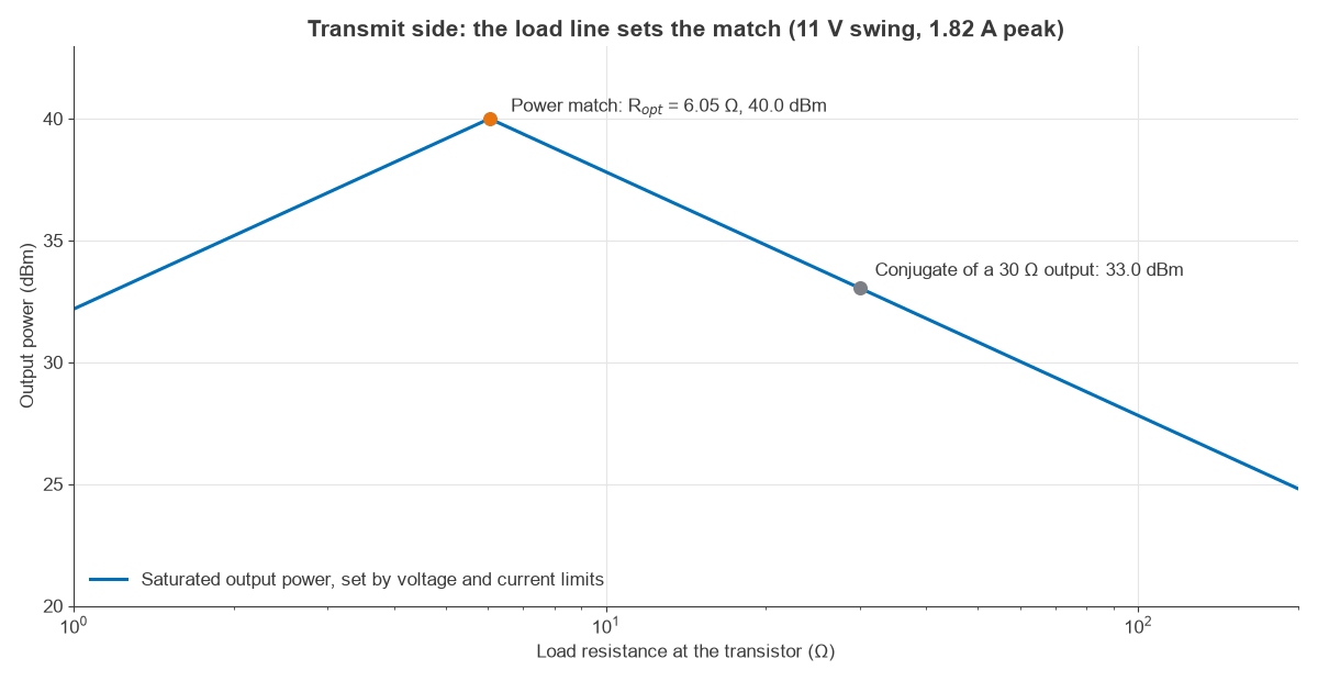
A small-signal amplifier gives maximum gain with a conjugate match. A power amplifier does not, because its output is limited by voltage swing and peak current instead of its small-signal output resistance. The best load is the one that uses both limits at once:
Ropt = Vswing2 / (2 Pout)
Above Ropt the voltage clips first, and below it the current does. Figure 1 plots both limits. This simple load-line view is the starting point for the full load-pull method, and the result depends on the amplifier mode described in power amplifier classes.
Worked example: a 10 W, 900 MHz output match
Take a device with an 11 V peak swing that must deliver 10 W (40 dBm) at 900 MHz. Output capacitance is assumed to be absorbed already.
- Load line: Ropt = 112 / (2 × 10) = 6.05 Ω, with a peak current of 11 / 6.05 = 1.82 A.
- Conjugate alternative: if the small-signal output resistance were 30 Ω, a conjugate load would limit output to 112 / (2 × 30) = 2.02 W, or 33.0 dBm. That is 7.0 dB less power.
- Network Q: an L network from 6.05 Ω to 50 Ω has Q = √(50 / 6.05 − 1) = 2.70.
- Components: series reactance 2.70 × 6.05 = 16.3 Ω gives L = 2.88 nH. Shunt reactance 50 / 2.70 = 18.6 Ω gives C = 9.53 pF.
- Loss: with an inductor Q of 50, the network passes 1 / (1 + 2.70 / 50) of the power, a loss of 0.23 dB. Delivering 10 W then means 0.54 W of heat in the network.
The low-pass form also attenuates harmonics, which is why it suits a transmitter. A larger step, or the need for more bandwidth, moves the design toward pi and T networks or broadband matching. Component current and voltage ratings need checking in every case, since a shunt capacitor or series inductor in a resonant network can carry more than the load current.
Matching circuits for the receiver
An LNA is usually matched for noise. Its noise figure depends on the source reflection coefficient Γs:
F = Fmin + 4 rn |Γs − Γopt|2 / [(1 − |Γs|2) |1 + Γopt|2]
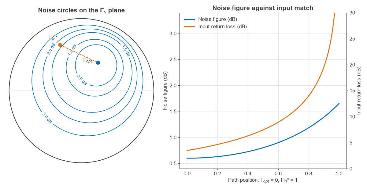
The minimum occurs at Γopt, which is set by the device’s noise parameters and normally differs from the conjugate of the input reflection Γin*. Loci of constant noise figure form circles on the Smith chart, shown in Figure 2. The article on noise figure covers the definitions.
Worked example: noise match against input match
Assume an LNA with Fmin = 0.6 dB, Γopt = 0.45∠60°, rn = 0.2 and Γin = 0.7∠−115°, treated as unilateral. The values illustrate the method and do not describe a specific part.
| Source setting | Noise figure | Input return loss |
|---|---|---|
| Γs = Γopt (noise match) | 0.60 dB | 3.5 dB |
| Midpoint of the path | 0.80 dB | 7.4 dB |
| Γs = Γin* (conjugate match) | 1.65 dB | Ideal match |
The full noise match reflects a large share of the incoming power, which costs about 2.6 dB of gain at the input and upsets any band filter ahead of the LNA. The midpoint keeps most of the noise benefit at 0.20 dB above minimum and doubles the return loss in decibels. That is the usual compromise. Inductive source degeneration is a common way to bring Γopt and Γin* closer together, a technique covered in the design of radio LNAs.
Resistance matching with an attenuator or a resistive feedback network gives a clean broadband input, but any resistor ahead of the first gain stage adds noise. Such methods suit the later stages of a chain, where cascaded noise figure shows that their effect is smaller.
Why network loss counts differently
The same 0.5 dB of loss has very different effects on each side. At the output of a 10 W transmitter it burns 1.09 W, which is a thermal and efficiency cost, and it reduces radiated power by 0.5 dB. Ahead of an LNA it adds 0.5 dB directly to system noise figure, so a 0.6 dB LNA becomes a 1.1 dB receiver front end. The receiver network therefore gets the highest-Q parts, the shortest traces and as few elements as possible.
Most radios share one antenna through a T/R switch, a duplexer or a circulator. The antenna is normally matched to 50 Ω at the shared port, as described in antenna matching, and each path then transforms 50 Ω to its own target. Keeping the two functions apart allows each to be measured and tuned alone.
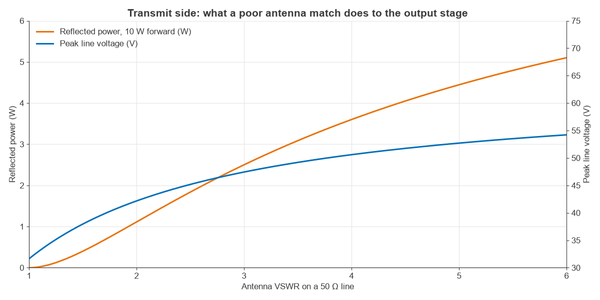
Antenna mismatch also behaves differently in each direction. On receive it mostly costs a little signal. On transmit it returns power to the amplifier. Figure 3 shows the effect for 10 W forward power. At a VSWR of 3, 2.5 W is reflected, the mismatch loss is 1.25 dB, and peak voltage on the line rises from 31.6 V to 47.4 V. VSWR and return loss covers the conversions.
Impedance tuning for changing antennas
An antenna’s impedance shifts with hand position, enclosure and nearby objects. Impedance tuning uses a network with switched or varactor elements to follow those changes. A closed-loop tuner samples forward and reflected power through a coupler and steps toward a better match. The transmit path is the usual priority, since the amplifier is the part at risk. Tuner loss then counts in both directions, so its benefit should be judged on the receiver noise figure too.
Frequently asked questions
Should a transmitter and a receiver use the same matching network?
Usually not. A shared antenna match to 50 Ω is common, but the amplifier networks differ because the transmitter targets a load line and the receiver targets a noise match.
Why is a power amplifier not conjugate matched?
Output power is limited by voltage and current swing, not by small-signal output resistance. The load that uses both limits fully is normally different from the conjugate, and using the conjugate would clip early at lower power.
Why is an LNA not conjugate matched?
The source impedance that minimizes noise differs from the one that maximizes gain. Designers accept some input mismatch to get closer to the minimum noise figure, or adjust the device so that the two points move together.
What is a matching network in RF?
It is a circuit of reactive elements or transmission lines that transforms one impedance into another with little loss. The impedance matching calculator computes L-network values directly.
Related topics
See the RF design section for the wider picture, the RF amplifiers hub for power and low-noise stages, and the RF noise hub for receiver sensitivity.