


The main benefits of beamforming in wireless communication are a stronger signal at the receiver, longer range, less interference and more capacity. An array of N antennas adds up to 10 log10(N) dB of SNR, so 8 antennas add 9 dB, which can triple the data rate at the cell edge. The costs are hardware, overhead and sensitivity to movement, and they decide whether beamforming is worth having on a given link.
This page puts numbers on both sides. To learn how the beam forms, start with MIMO beamforming basics or the fuller beamforming article. For how networks apply it, see beamforming techniques in cellular systems.
How beamforming in wireless communication improves a link
A single antenna radiates power over a wide angle, and most of it misses the receiver. Beamforming weights each antenna so the signals add in phase at the receiver, so amplitude adds with N and received power with N2. Splitting a fixed transmit power across N elements divides that by N, which leaves a net array gain of N, or 10 log10(N) dB. If each element has its own amplifier at full power, the EIRP gain becomes 20 log10(N) dB.
Every benefit below follows from that one gain, spent in a different way.
Benefit 1: stronger signal and higher data rates
Capacity depends on SNR as log2(1 + SNR). The gain matters most when SNR is low, because the log is close to linear there. At high SNR the same decibels add only a fraction more.
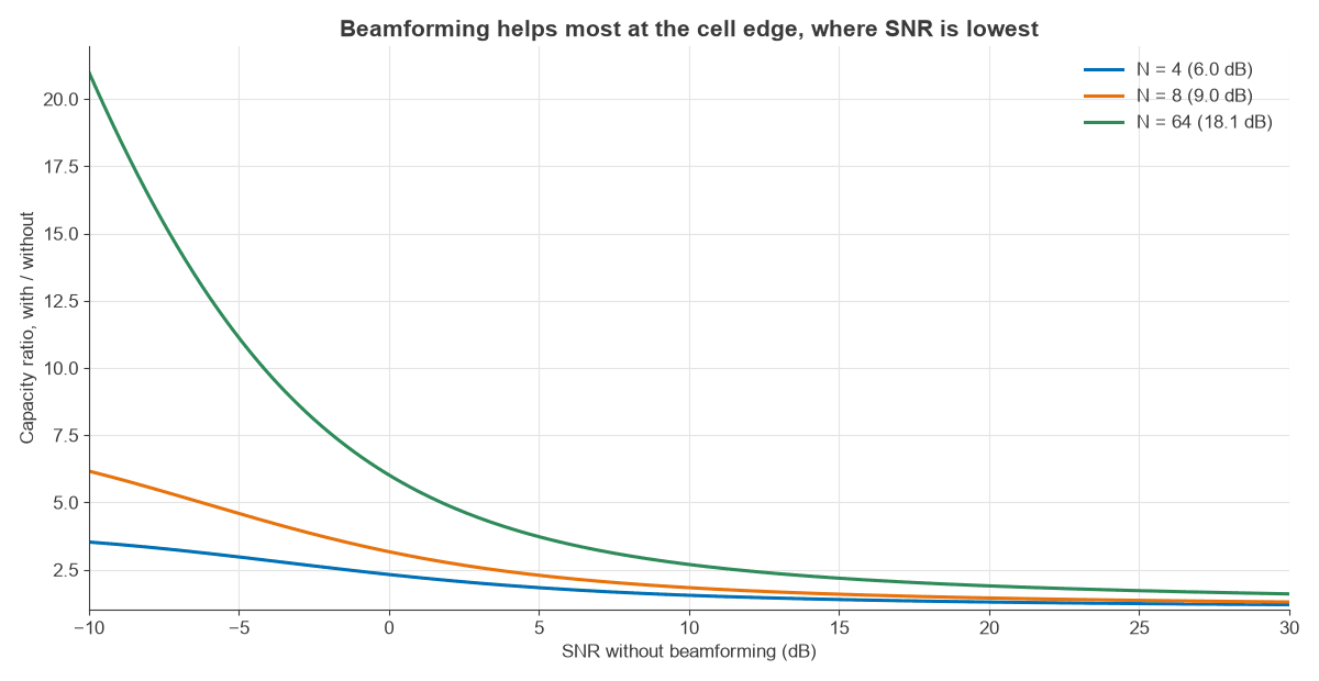
This is why operators care about beamforming at the cell edge. It is also why a phone already next to the access point gains little.
Benefit 2: extended range and coverage
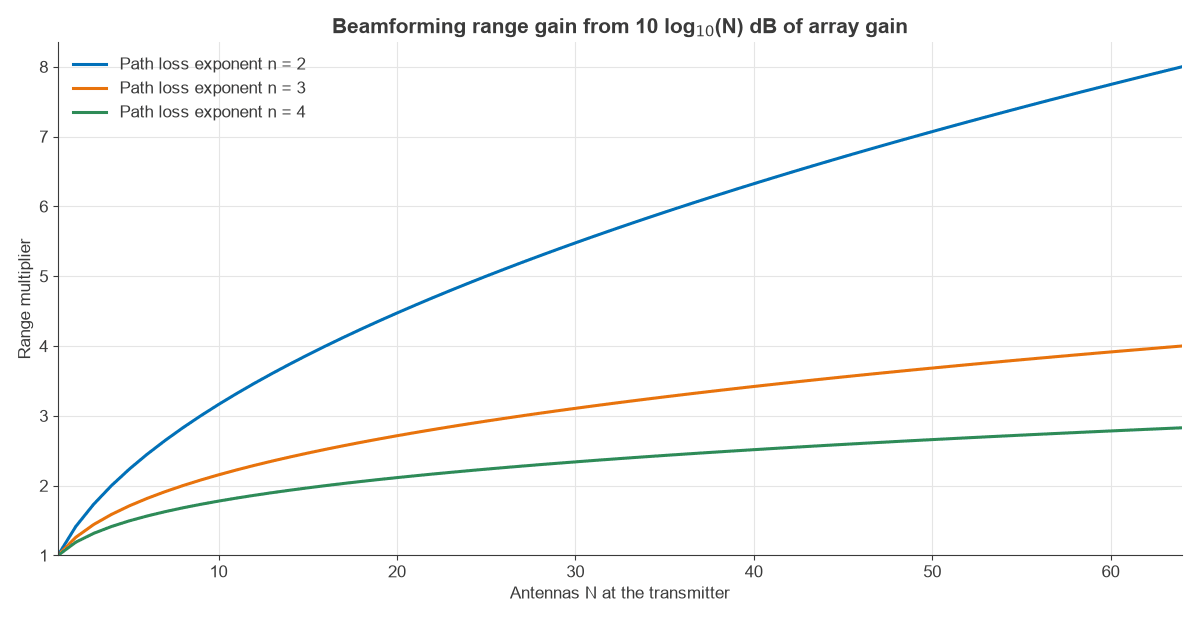
With path loss proportional to dn, extra gain G in dB extends range by a factor of 10G/(10n). The value of n sets how far that goes:
| Environment | Path loss exponent n | Range multiplier, 9 dB | Area multiplier |
|---|---|---|---|
| Free space | 2 | 2.83 | 8.0 |
| Open outdoor | 3 | 2.00 | 4.0 |
| Urban | 3.5 | 1.81 | 3.3 |
| Dense urban or indoor | 4 | 1.68 | 2.8 |
The last column explains the commercial case. Coverage area rises with range squared, so 9 dB in an urban cell can reduce the number of sites for a given area by about a factor of three. For uplink-limited links the benefit also needs receive beamforming at the base station. The link budget calculator shows how the gain enters a full budget.
Benefit 3: reduced interference
A beam puts less energy in other directions, which helps neighbouring links. An 8-element array steered to broadside has an array factor of -13 dB at 20 degrees off axis and a null at 30 degrees. If the interferer’s direction is known, the weights can place a null on it deliberately. MIMO precoding covers the methods.
Lower interference also lifts cell-wide capacity, since every cell’s beams spill less into the next. In real multipath this benefit is smaller than a clean pattern suggests, because a user’s energy arrives from many directions.
Benefit 4: more capacity through spatial reuse
Narrow beams allow two or more users to share one time-frequency resource, which is MU-MIMO. Instead of raising one link’s SNR, the array spends its gain on separating streams. Massive MIMO spectral efficiency shows the result at large scale, and user scheduling in MIMO systems explains how users are paired.
Worked example: what 8 antennas are worth
Consider an urban 3.5 GHz cell (n = 3.5). The array has 8 antennas and an ideal gain of 10 log10(8) = 9.0 dB. Assume 2 dB of practical losses, leaving 7 dB.
| User | SNR before | Rate before (b/s/Hz) | Rate with 9 dB | Rate with 7 dB | Ratio at 7 dB |
|---|---|---|---|---|---|
| Cell edge | 0 dB | 1.00 | 3.17 | 2.59 | 2.6 |
| Near site | 25 dB | 8.31 | 11.31 | 10.63 | 1.3 |
For the same 0 dB user, range can grow by 1.81 times if the rate is held fixed and all 9 dB goes to coverage. After the 2 dB of losses the multiplier is 1.58. So 8 antennas can deliver about 2.6 times the cell-edge rate, or about 2.5 times the area (3.3 times with no losses), but not both at once.
Beamforming disadvantages
The gain has a price, and it shows in five places.
- Hardware. Each digital chain needs data converters, a mixer and an amplifier, so DC power and cost rise with the chain count before any extra baseband work. Phased array design covers the cost per element.
- Channel knowledge. Beamforming needs recent CSI. Sounding uses air time, and feedback uses uplink capacity, and both grow with antenna count.
- Calibration. Phase and gain errors between chains blur the beam and raise sidelobes.
- Scan loss and blockage. Arrays lose gain far off boresight, and a narrow beam at mmWave can be blocked by a hand or a body.
- Sensitivity to motion. A beam aimed at last millisecond’s channel can miss this one.
The last item is often underrated. In Rayleigh fading, with correlation ρ between the estimate and the current channel, the gain falls from N to about ρ2N + (1 – ρ2). Clarke’s model gives ρ = J0(2πfDT), where fD is the Doppler shift and T the age of the CSI.
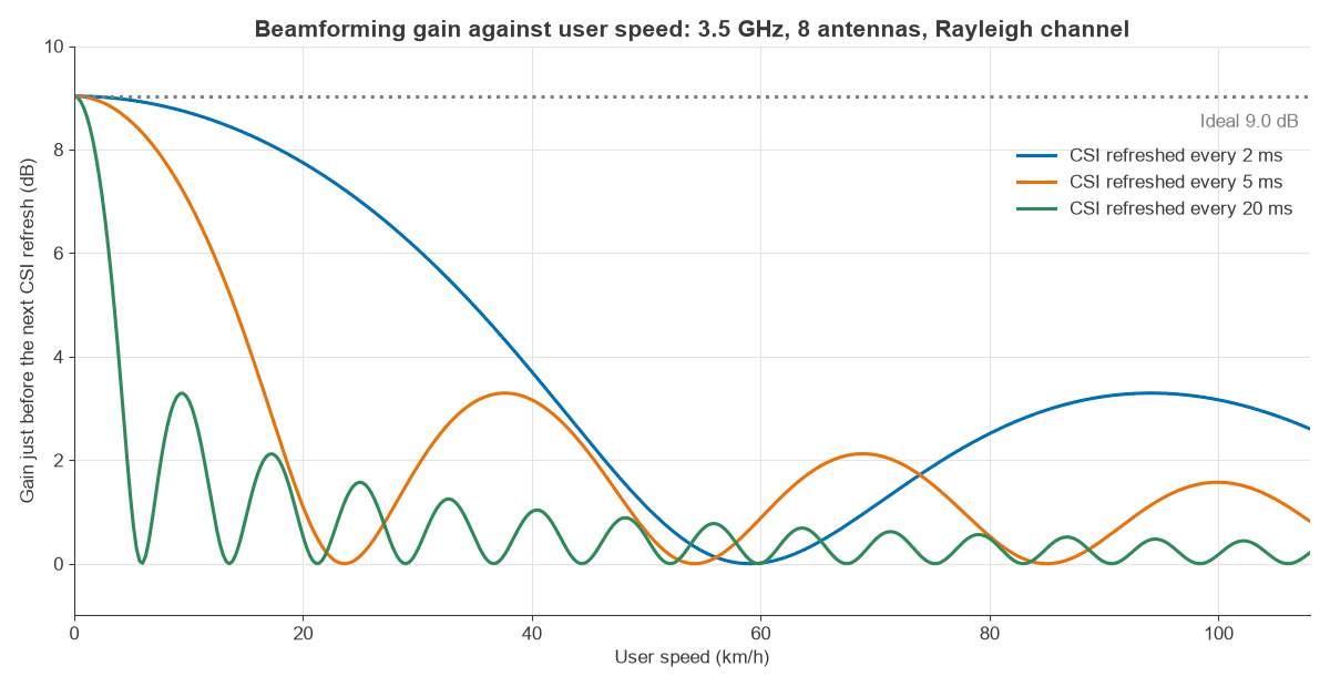
At 3.5 GHz, a pedestrian at 1.5 m/s has fD = 17.5 Hz. With 5 ms-old CSI, ρ = 0.93 and the gain is 8.5 dB. With 20 ms-old CSI, ρ = 0.11 and the gain is only 0.4 dB. A vehicle at 10 m/s with 5 ms-old CSI keeps 3.2 dB. Those are worst-case numbers for rich scattering. Beams that follow a dominant path rather than the fast fading, such as a grid of beams, keep most of their gain because the path direction changes much more slowly.
Is beamforming worth it?
It depends on what limits the link.
| Situation | Worth it? | Why |
|---|---|---|
| Weak signal at cell edge | Yes | Largest rate gain |
| mmWave link | Essential | Path loss cannot be closed otherwise |
| Crowded cell, many users | Yes | Enables MU-MIMO |
| Strong signal already | Little gain | Capacity is logarithmic |
| Fast users in rich scattering | Limited | CSI ages before use |
| Small, low-cost IoT device | Rarely | Power and cost dominate |
The table assumes the gain is the only thing being bought. A fair comparison sets beamforming against other ways of spending the same money: more bandwidth, a smaller cell or a better antenna. Extra bandwidth raises rate at every SNR, while beamforming mostly helps weak links, so the two suit different problems. If the link budget is the limit, beamforming is hard to beat, and if capacity in a crowded cell is the limit, MU-MIMO is the part that pays.
Wi-Fi is a good everyday case. Access points since 802.11ac can sound the channel and steer towards a compatible client, typically with two to four antennas. That is up to 3 to 6 dB of gain, which is noticeable a room or two away and hardly matters a metre from the router.
Frequently asked questions
What is beamforming in wireless communication?
It is the use of several antennas with chosen phase and amplitude weights so that signals add at the receiver, or so that a receiver picks out one direction. It increases SNR without extra bandwidth.
How does beamforming improve network service?
It raises cell-edge rates, extends coverage, reduces interference between cells and lets users share a resource block. Users notice steadier speed in weak-signal areas, and the network gains capacity.
What are the disadvantages of beamforming?
They are the cost and power of extra RF chains, overhead for CSI, calibration, and reduced gain for fast users. At mmWave, blockage is also a problem.
Is beamforming the same as MIMO?
No. Beamforming uses several antennas to focus one signal, while MIMO more broadly covers sending several streams using antennas at both ends. Most modern systems do both, as described in MIMO and multiple antenna systems.
Related topics
Antennas and propagation in radio design explains the path loss used here, and channel state information covers the channel knowledge beamforming depends on. For the wider topic area, see MIMO, antennas and the RF design hub.