


Power in RF systems is the rate at which energy is delivered by a signal, usually stated as average power in watts or dBm. It depends on voltage, current and the phase between them, so only the resistive part of a load absorbs it. In a complete system, power has to be followed from the DC supply through the amplifier and feed line to the antenna, because each step decides how much reaches the air and how much becomes heat.
Engineers need several power terms: average, peak, forward, reflected, available and radiated. This article defines them and works through three examples: a complex load, a high-VSWR load and a complete transmitter budget.
RF Power from Voltage and Current
For a sinusoid, the instantaneous power is p(t) = v(t) i(t). Average power, in terms of peak phasors, is:
P = ½ Re{V I*} = ½ |V||I| cos φ
where φ is the phase between voltage and current. In a pure resistance, φ = 0. In a pure reactance, φ = ±90° and energy simply flows in and back each cycle, so the average is zero. Reactive energy is stored, not consumed, and yet it still loads the circuit with current and voltage.
Worked Example: A Complex Load
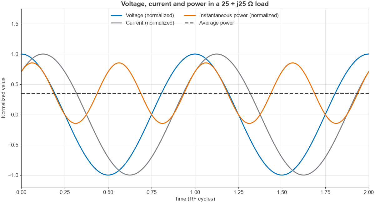
Apply a sine wave of 2 V peak to a load of 25 + j25 Ω. The impedance magnitude is 35.4 Ω at an angle of 45°, so:
- Peak current: 2 / 35.4 = 56.6 mA, lagging the voltage by 45°
- Average power: ½ × 2 × 0.0566 × cos 45° = 40 mW
- Apparent power: ½ × 2 × 0.0566 = 56.6 mVA
- Power factor: 0.707
As a check, ½ I2R = ½ × 0.05662 × 25 = 40 mW, so all the real power is in the resistive part. Figure 1 shows the waveforms. Instantaneous power goes slightly negative for part of each half cycle, when the reactance hands energy back to the source. It oscillates at twice the signal frequency.
Units of RF Power
Power spans a huge range across a radio, so engineers use a logarithmic scale. Power in dBm is 10 log10(P / 1 mW), so 0 dBm is 1 mW, +30 dBm is 1 W, and a receiver may work with signals below -100 dBm. See dB, dBm, dBW and dBc for the rules. Gains and losses in dB are added to dBm levels, which is what makes a chain easy to calculate.
Average, Peak and Envelope Power
Several definitions are in use, and it is important to know which one a specification refers to:
- Average power: taken over many cycles and many symbols. It sets the thermal load and the link budget.
- Peak envelope power: the average over one RF cycle, at the highest point of the envelope. It sets compression and voltage stress.
- Peak-to-average power ratio (PAPR): the ratio of the two, in dB. It is 0 dB for a constant-envelope signal, 3 dB for two equal tones and often 8 dB to 12 dB for OFDM.
- Available power: the most a source could deliver to a conjugate-matched load.
- Delivered power: what the load actually absorbs.
The distinction between available and delivered power is the subject of impedance matching. The practical measurement of these quantities is described under measuring amplitude and power in RF signals.
Forward, Reflected and Net Power
On a transmission line with a mismatched load, two waves exist: forward and reflected. The net power delivered is the difference between them:
Pnet = Pfwd – Prev = Pfwd(1 – |Γ|2)
Worked Example: 100 W Into a 3:1 VSWR
A 100 W forward wave travels on a 50 Ω line to a load with a VSWR of 3:1. Then:
- |Γ| = (3 – 1) / (3 + 1) = 0.5
- Reflected power: 100 × 0.25 = 25 W
- Net power: 75 W
- Peak voltage of forward wave: √(2 × 100 × 50) = 100 V
- Peak voltage at a standing-wave maximum: 100 × 1.5 = 150 V
- Peak current at a standing-wave maximum: 2 × 1.5 = 3 A
So the line must withstand 150 V peak even though a matched system at 100 W would see only 100 V. Connectors, capacitors and PCB clearances in the path must be rated for that level, and in a transmitter the reflected wave changes the load seen by the amplifier. See VSWR and return loss for the conversions.
Following Power Through a Transmitter
A transmitter chain converts DC power to RF, with losses at each step. Power amplifier efficiency is given in two common forms:
Drain efficiency: η = Pout / PDC
Power-added efficiency: PAE = (Pout – Pin) / PDC
Worked Example: A 10 W Transmitter Budget
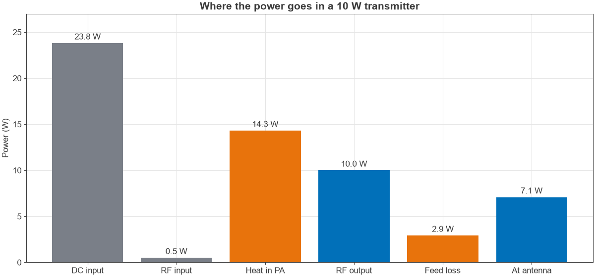
A power amplifier delivers 10 W (+40 dBm) with 13 dB gain and 42% drain efficiency. It feeds a line with 1.5 dB loss to a 9 dBi antenna. The signal has 8 dB PAPR.
- Input drive: 40 – 13 = +27 dBm = 0.50 W
- DC power: 10 / 0.42 = 23.8 W
- PAE: (10 – 0.50) / 23.8 = 39.9%
- Heat in the amplifier: 23.8 + 0.50 – 10 = 14.3 W
- Power at the antenna: 40 – 1.5 = +38.5 dBm = 7.08 W, so 2.92 W is lost in the feed
- EIRP: 38.5 + 9 = +47.5 dBm = 56.2 W
- Peak envelope power at the PA output: 40 + 8 = +48 dBm = 63.1 W
- Peak voltage at that level in 50 Ω: √(2 × 63.1 × 50) = 79.4 V
Figure 2 shows the same budget as a chart. Three results stand out. The amplifier produces more heat than RF, and removing that heat is a design task of its own, as covered in thermal design for RF power amplifiers. A feed loss of 1.5 dB costs nearly 30% of the RF power. And the amplifier must have peak capability well above its average output, or the signal peaks will compress. Note also that EIRP is a measure of concentration in one direction, not of generated power; the antenna adds no energy, and the 56.2 W is what an isotropic radiator would need to match it.
Efficiency and Back-Off
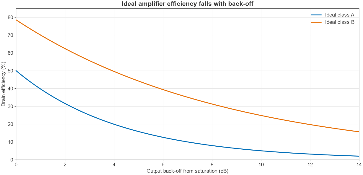
Because the amplifier must have room for signal peaks, it runs below saturation on average. This is called back-off, and it costs efficiency. For ideal stages, efficiency falls in a predictable way:
- Ideal class A: η = 50% × (Pout / Psat)
- Ideal class B: η = 78.5% × √(Pout / Psat)
At 8 dB back-off, class A efficiency falls to 7.9% and class B to 31.3%, as Figure 3 shows. Real amplifiers do worse. This is why Doherty amplifiers, envelope tracking and digital predistortion are used in systems with high PAPR. The power amplifier classes page compares the options, and P1dB compression describes what happens at the top of the range.
Receiver Power Levels
Power at the other end of a link is tiny. Free-space and path losses often exceed 100 dB, so a received signal may be near -90 dBm, which is about one picowatt. The floor is set by thermal noise, which is -174 dBm/Hz at room temperature; see thermal noise and kTB. The receiver must also survive large signals, so its dynamic range is a power specification too. A link budget ties the transmit and receive sides into a single table.
Frequently Asked Questions
What is the difference between peak and average RF power?
Average power is the mean over many cycles and sets heat and range. Peak power is the highest envelope level and sets compression and voltage stress. The difference between them, in dB, is the PAPR.
What is EIRP?
Effective isotropic radiated power is the power fed to the antenna, multiplied by its gain relative to an isotropic radiator. In logarithmic units, EIRP in dBm equals transmit power in dBm, minus feed loss, plus antenna gain in dBi. It is the figure most regulators limit.
Why does a power amplifier get hot?
All the DC power that does not leave as RF becomes heat. At 42% efficiency, the amplifier turns more power into heat than into signal.
Does reflected power damage an amplifier?
It can. Reflected power changes the load the amplifier sees, which can raise device voltage, current or dissipation. Many transmitters use isolators or VSWR protection that reduces drive when the reflection is high.
Related Topics
Continue with the RF amplifiers hub, the RF fundamentals hub and the antennas and propagation section. The RF calculators include power conversion tools.