


Amplitude modulation and demodulation are the two halves of an AM link: the transmitter puts the message on the carrier envelope, and the receiver recovers it with an envelope detector, a product detector or a synchronous detector. The envelope detector is the simplest and needs no carrier reference. Product and synchronous detectors cost more but keep working on suppressed-carrier signals and at low carrier-to-noise ratio.
This article concentrates on the receive side. The modulation itself, including the modulation index and sidebands, is covered in Amplitude Modulation: Understanding the Basics, and the wider family of carrier methods in continuous wave modulation. Here the focus is detector design, with one circuit worked through to real component values.
Amplitude Modulation and Demodulation: The Signal Model
An AM signal with a message m(t) scaled so that |m(t)| ≤ 1 is written as:
s(t) = Ac[1 + μ m(t)] cos(2πfct)
The envelope is Ac[1 + μ m(t)], and μ is the modulation index. As long as μ ≤ 1 the envelope never crosses zero, so its shape is an exact copy of the message plus a DC offset. That single fact is why a simple rectifier works. With μ above 1 the envelope folds at zero and only a coherent detector can recover the message.
Demodulation therefore has two possible goals: measure the size of the signal, which ignores carrier phase, or multiply by a copy of the carrier, which depends on it. Every AM demodulation technique is a version of one of these two.
Types of AM Demodulation Techniques
| Detector | Needs carrier reference? | Handles DSB-SC and SSB? | Main weakness |
|---|---|---|---|
| Envelope (diode and RC) | No | No | Diagonal clipping, threshold at low CNR |
| Square-law | No | No | Second-harmonic distortion |
| Product detector | Yes, free-running BFO is enough for SSB voice | Yes | Frequency or phase error |
| Synchronous (PLL or Costas) | Yes, recovered from the signal | Yes | Loop complexity, acquisition time |
| Digital I/Q | No, magnitude can be taken directly | Yes, with carrier recovery | Needs an ADC and DSP |
Envelope Detector: How AM Demodulation Works in a Diode Circuit
An envelope detector is a diode followed by a parallel RC load. On each positive carrier peak the diode conducts and charges C. Between peaks the diode is off and C discharges through R. The output follows the peaks, with a small sawtooth ripple at the carrier frequency. A DC block then removes the 1 in 1 + μm(t), and that DC term is commonly reused for automatic gain control.
The time constant is squeezed from two sides:
- It must be long compared with the carrier period, 1/fc, or ripple becomes large.
- It must be short enough for the capacitor to discharge as fast as the envelope falls.
Diagonal clipping
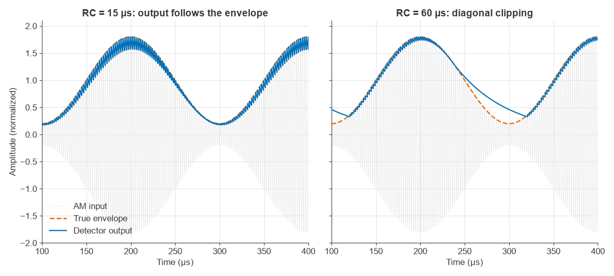
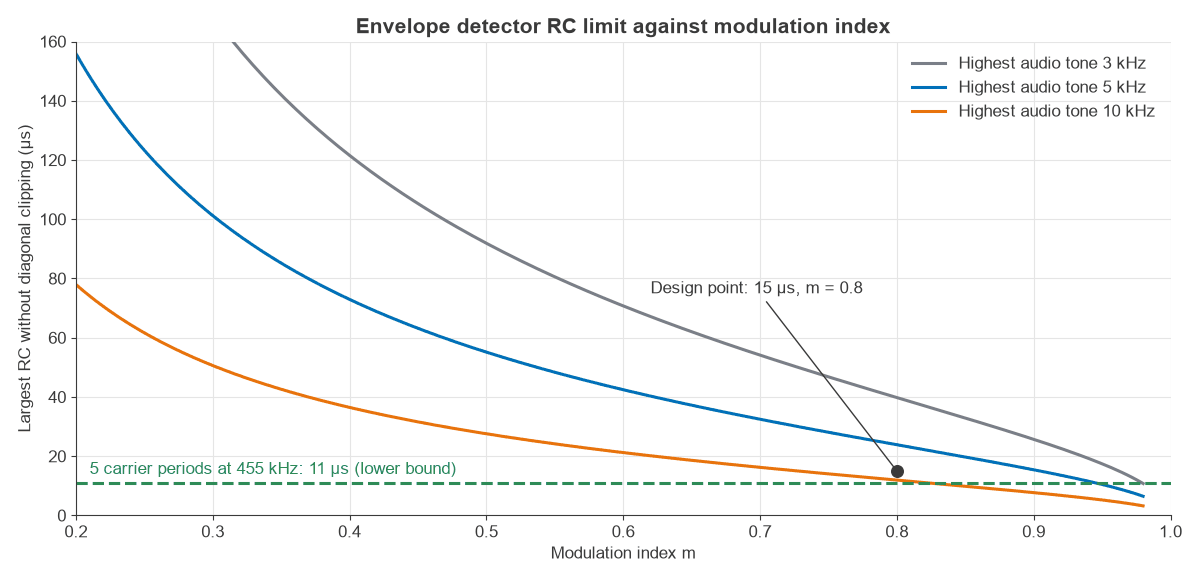
If RC is too long, the voltage on the capacitor cannot fall as fast as the envelope, and the output traces an exponential instead of the message. This is diagonal clipping. For a tone at fm, the condition for tracking at every point on the waveform is:
RC ≤ √(1 − μ²) / (2π fm μ)
The limit tightens quickly as μ approaches 1, because the steepest part of the envelope gets steeper and the trough gets deeper.
Negative peak clipping
The audio stage after the detector loads it through a coupling capacitor, so the AC load Rac is lower than the DC load Rdc. The capacitor holds a DC voltage, and the troughs of the envelope cannot go below it. The result is a flat-bottomed output unless:
μ ≤ Rac / Rdc
Diode drop and small signals
A real diode needs a forward voltage, roughly 0.2 to 0.3 V for a Schottky and 0.6 V for a silicon junction. Well above that voltage the detector is close to linear. At low levels the diode behaves as a square-law device, which adds distortion, so receivers place enough IF gain ahead of the detector to keep it in its linear region. Square-law detection of a tone gives a second harmonic at μ/4 relative to the fundamental: 20% at μ = 0.8.
Worked Example: Designing a 455 kHz Envelope Detector
Take an AM receiver with a 455 kHz IF, a highest audio tone of 5 kHz and μ = 0.8. The detector load is 10 kΩ, and the next stage has a 47 kΩ input resistance.
- Carrier period: 1/455 kHz = 2.20 µs.
- Diagonal clipping limit: √(1 − 0.64) / (2π × 5 kHz × 0.8) = 23.9 µs.
- Choose C = 1.5 nF, which gives RC = 15 µs. This is 6.8 carrier periods, and 63% of the limit.
- Ripple: 1 − exp(−2.20/15) = 13.6% of the peak, at 455 kHz. It lies far above the audio band, and a small following low-pass filter removes it.
- AC load: 10 kΩ in parallel with 47 kΩ = 8.25 kΩ, so the negative peak limit is 8.25/10 = 0.825.
This design only just clears the negative peak limit at μ = 0.8. Raising the following input resistance to 100 kΩ would move the limit to 0.909. The simulated output in Figure 1 tracks with 15 µs and clips with 60 µs, as the formula predicts.
Product Detector and Coherent AM Demodulation
A product detector multiplies the received signal by a local carrier with phase error φ, then low-pass filters. For the AM signal above:
v(t) = ½ Ac[1 + μ m(t)] cos φ + a term at 2fc
The term at twice the carrier falls to the filter and the message remains, scaled by cos φ. The scaling is the price of coherent detection:
| Phase error | Output change |
|---|---|
| 10° | −0.13 dB |
| 30° | −1.25 dB |
| 45° | −3.01 dB |
| 60° | −6.02 dB |
| 90° | Output nulled |
Small errors barely matter, but a slowly drifting oscillator would fade the audio in and out. A double-sideband suppressed-carrier signal has this problem in its worst form, because a 100 Hz offset multiplies the audio by a 100 Hz cosine, so the output nulls 200 times a second. Single sideband is more forgiving. A 100 Hz offset just shifts every audio tone by 100 Hz, so an SSB voice receiver can use a free-running beat frequency oscillator. The same arrangement receives Morse, as shown in the continuous wave modulation article.
In hardware the multiplier is usually a mixer, such as a diode ring or a Gilbert cell. The I/Q modulator and demodulator article describes the quadrature version used in direct-conversion and software-defined receivers.
Synchronous Detection: Recovering the Carrier
A synchronous detector is a product detector whose oscillator is locked to the incoming signal. For AM with a carrier, a phase-locked loop tracks the carrier line directly. For suppressed-carrier signals, a Costas loop uses in-phase and quadrature mixers, with the product of the two outputs acting as the phase error signal. Both ideas are the same ones used for digital carriers in PSK detection.
The advantage shows up during selective fading on shortwave. When the carrier drops into a fading notch, an envelope detector produces severe distortion because the envelope no longer has the right shape. A synchronous detector with a slow loop holds its reference through the fade, and can choose the cleaner sideband.
In a digital receiver, the signal is mixed to baseband I and Q samples first. The magnitude √(I² + Q²) is a perfect envelope detector with no diode drop or RC limit, and the projection on a recovered carrier is a synchronous detector. Both can run from the same samples.
AM Demodulation SNR and the Threshold Effect
AM wastes power in the carrier. The fraction of power in the sidebands for a tone is η = (μ²/2) / (1 + μ²/2), which is 24.2% at μ = 0.8. Above threshold both detectors give an output SNR of 2η times the carrier-to-noise ratio, taken here as total received power over noise in the 2W signal bandwidth, or 3.1 dB below CNR at this index. A CNR of 20 dB gives 16.9 dB, and the simulation agrees to 0.1 dB.
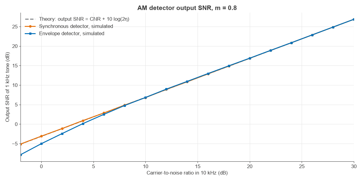
The curves match down to about 8 dB. Below that, noise rather than the carrier dominates in the envelope, and the message starts to multiply with noise. At 0 dB CNR the envelope detector gives −5.0 dB against −3.1 dB for the synchronous detector, and the gap reaches 2.8 dB at −2 dB CNR. Synchronous detection has no such threshold, so it stays on the straight line. For the noise terms behind these figures, see SNR and Eb/N0.
Frequently asked questions
What is the difference between modulation and demodulation?
Modulation places a message on a carrier by varying its amplitude, frequency or phase. Demodulation is the receiver process that extracts the message again. In AM, modulation sets the envelope and demodulation measures it or multiplies it by a carrier reference.
Why is an envelope detector used in AM receivers?
It uses a single diode, a resistor and a capacitor, needs no local oscillator, and gives a usable result on signals with a full carrier. Those properties made it the default for broadcast receivers. It cannot demodulate DSB-SC or SSB.
What causes diagonal clipping in an AM detector?
The RC time constant is too long for the capacitor to discharge at the rate the envelope is falling. Reduce RC, or limit the modulation index or highest audio frequency.
What is synchronous detection in AM?
It is coherent demodulation using a carrier reference locked to the received signal by a PLL or Costas loop. The output follows the message with no threshold effect, and the method works with suppressed-carrier signals.
Related topics
Other members of this group include frequency modulation, amplitude shift keying, frequency shift keying and pulse amplitude modulation. The modulation, EVM and PAPR part of the Radio Architectures series covers the transmitter side, and RF fundamentals collects the background.