In 2021, it’s standard to expect wireless technologies in cell phones, computers, and audio accessories. However, RF designs are also making their way into industrial sectors as well—for instance, in automation, predictive maintenance, and human-machine interfaces (HMI).
These applications often tap into the 2.4 GHz ISM (industrial, scientific, medical) band, which is an unrestricted, overutilized, legacy domain for Wi-Fi 4. Unfortunately, the spectrum region’s popularity means that devices supporting this legacy system may trade off the benefits offered by 5 GHz Wi-Fi.
u-blox Advances Monolithic Integration
Contents
This week, u-blox announced a new radio chip series, the MAYA-W1, that addresses these concerns and provides a monolithic multi-radio solution. These chips incorporate a 2.4 GHz and 5 GHz radio and supports the Bluetooth Classic mode and BLE (Bluetooth low-energy).
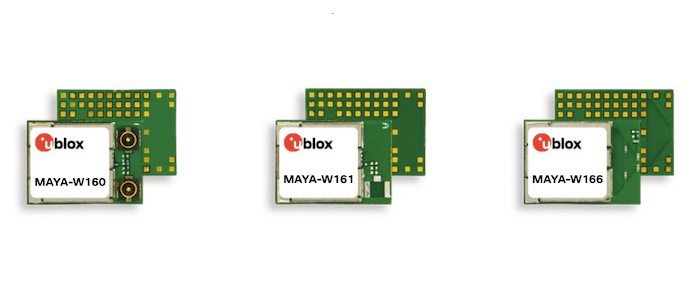
The 10.4 mm x 14.3 mm x 2.5 mm monolithic chip is said to simplify incorporating wireless connectivity into applications with its three interface format options: an embedded antenna, and U.FL connectors, or antenna pins.

The MAYA-W1 family from u-blox. Image used courtesy of u-blox
In the press release, Stefan Berggren, u-blox’s senior product marketing manager, explains, “Wi-Fi 4 continues to be the most used technology in our target segments, but there is concern over congestion of the 2.4 GHz band.” To overcome this issue, MAYA-W1 incorporates dual-band capability, making it a contender for IoT applications.
How exactly do devices like the MAYA-W1 function to bring dual-band capability to such embedded designs? Engineers might consider three factors: architecture, antenna geometries, and RF front-end modules.
Electronic Architecture for Dual-band Applications
Fundamentally, dual-band (or multi-mode) radios can operate within two or more distinct RF spectrum regions. Operating in both regions is possible with either conventional superheterodyne analog receivers or through direct conversion to a digital signal from the native GHz frequencies.
To accomplish modern RF sampling, designers must use direct conversion from received frequencies without converting the signal with a local oscillator (superheterodyne).

An example of a frequency division duplexing receiver architecture with a direct conversion. Image used courtesy of Texas Instruments
To process the filtered and amplified circuitry through DSP applications, an engineer must then use a multi-gigahertz throughput of high-end ADCs. This throughput greatly simplifies the RF architecture required to run multi-mode radio applications without limiting the possible modulations’ complexity.
Antenna Geometries Determine the “Fractional Bandwidth”
In addition to architecture, designers should also consider how antenna geometries can limit the coherently-receivable range of energies. To overcome this limitation, engineers can either build multiple antenna geometries into their device or generate a “multi-band” antenna that operates acceptably within the frequency ranges of interest.
The fractional bandwidth represents how wide-band an antenna is with respect to the center frequency of operation. It varies between 0 and 2, depending on the extent of the upper and lower band cutoff.
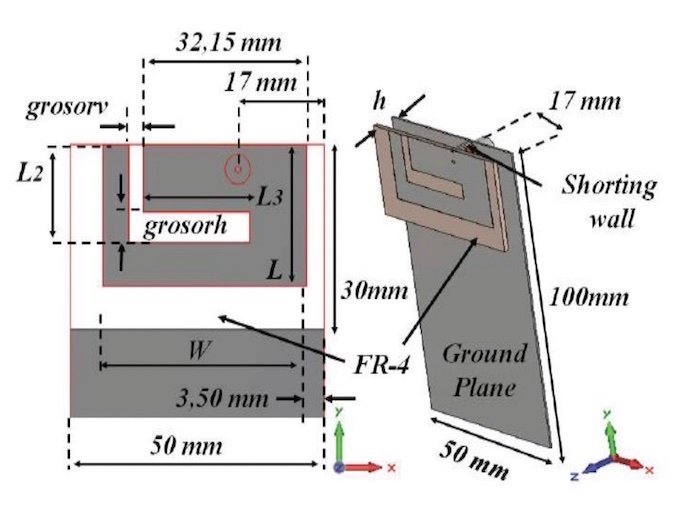
One of the most popular antenna geometries for wireless devices today is the planar inverted F antenna (PIFA).

A 3D rendering of a PIFA antenna designed by students at Universiti Malaysia Perlis. Image used courtesy of Munzer et al. and MATEC Web of Conferences
PIFA has gained popularity because it can be printed directly on a PCB. Additionally, it functions well in a wide range of RF applications, including GSM, Bluetooth, Wi-Fi, and several other cellular standards.
Despite the PIFA antenna’s success for use in the cellular and legacy ISM band, it is not appropriate for use at 5 GHz and 2.4 GHz simultaneously. Designers must use two antennas for the Wi-Fi 4 dual-band, which can then be diplexed into a single 50Ω transmission line on the PCB for post-reception processing.
Higher speeds and bandwidths with 5 GHz Wi-Fi lead to more complex PCB design because of transmission line effects, accounting for the various FEM sub-systems.
Complex RF FEM’s for Dual-band Applications
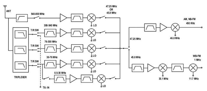
Beyond the antenna, the RF front-end module (FEM) must accommodate a more complex architecture to facilitate dual-band.

This image is an example of a multiplexed superheterodyne radio front-end. Image used courtesy of Virginia Tech
Pre-selection (through the use of a diplexer or multiplexer) is a process used to separate the signals received at the antenna into their respective energy bands for downconversion and processing.
Flexibility in Embedded Design
The MAYA-W1 serves as an interesting example of how these three design principles come together to offer dual-band capability. u-blox claims that it kept design flexibility as a key focus in developing the new module, offering both dual-mode Bluetooth (BLE and Classic) and Wi-Fi 4. To this end, the module is pre-integrated with NXP’s MCUXpresso development environment.
Devices that include dual-band capability are becoming increasingly useful in power management, EV charging, fleet management, telematics, and professional appliances, among others.
Do you have any experience with RF dual-band ranges, either in design or embedded programming? Let us know in the comments below.


