29 October 2020
Market demand for higher speeds and larger bandwidths drives the move from 4G to 5G. Going to higher frequencies makes the power amplifier application design even more challenging. For the customers of Ampleon, Bruco Integrated Circuits develops efficient PA modules for 4G/5G base station applications in the range of 0.6-4 GHz.
Featuring lower latency, higher capacity and increased bandwidth, 5G is a significant evolution of today’s 4G LTE (Long-Term Evolution) standard. The 5th generation of mobile networks has been designed to meet the steep growth in data and connectivity demand of modern society, the ever-expanding internet of things with billions of connected devices and tomorrow’s innovations. They’ll initially operate in conjunction with existing 4G networks before evolving to fully stand-alone networks in subsequent releases and coverage expansions.
5G applications operate in three frequency bands. The low-band (600-700 MHz) base station tower has a large area coverage with a ten kilometer radius, combined with a narrow bandwidth and speeds of 30-250 Mb/s. In the mid-band (3.4-3.8 GHz in Europe), the tower covers a radius of four kilometers and supports 100-900 Mb/s. Together, these are called sub-6 GHz bands. The high band (26-27.5 GHz) in the millimeter-wave (mm-wave) spectrum services a radius of less than one kilometer with typical speeds of 1-3 Gb/s. Higher frequencies bring higher bandwidth and speed, but lower area coverage.

To be able to send and receive more data simultaneously, and thus connect more users at the same time, 5G employs ‘massive’ MIMO (multiple input, multiple output) antennas, consisting of a very large number of antenna elements. Rather than broadcasting in all directions, beam steering technology allows the base stations to send the radio signal directly to the targets, with advanced signal processing algorithms determining the best path. Bundling all transmitted power to the user increases efficiency. 5G MIMO communication to mobile devices will ride the mm-wave (27 GHz).
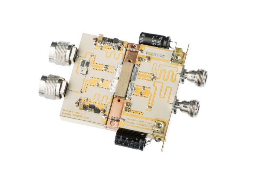
From the antenna, the base stations run a wired backhaul to a receiver/amplifier subsystem that boosts the cellular signal to the mobile device and an optical fiber connection to the core network. Typically, there are multiple amplifiers, each tuned to a specific frequency band, with power, efficiency and linearity as important parameters. For customers of Ampleon, Bruco Integrated Circuits designs so-called Doherty amplifier module prototypes, the schematic and PCB layout of which are used as a basis for base station equipment development and tests. These prototypes incorporate more broadband amplifiers, covering multiple frequency bands (eg 700-900 MHz or 1.8-2.3 GHz).
Ideal model
The specifications of the Doherty amplifier are a combination of requirements from wireless standards and Ampleon’s customers. The full set includes electrical specs like frequency range and output power but also mechanical specs like size constraints and PCB material. Incorporating these mechanical constraints already in the prototype design will make the integration process easier for the customer.

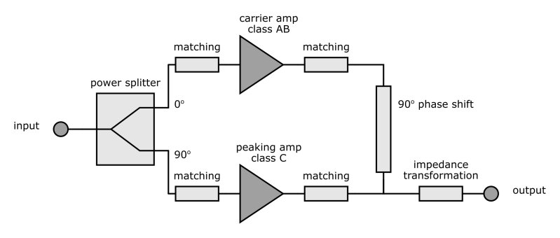
The Doherty topology is a very common choice for base station amplifiers. It consists of two separate paths, both of which serve a specific purpose. The carrier path is always amplifying the input signal and produces output power over a wide range of input powers. The peaking path is biased in class C, which means that it will only produce output power when the input signal is large enough. It’s used to amplify the high power peaks of the input, hence the name. When designed properly, this topology can produce a good efficiency over a wide output power range and with high linearity.
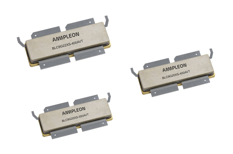
The most important component in a Doherty amplifier is, of course, the transistor itself. This component is selected to match the requirements with the best performance. The transistor data are provided by Ampleon in the form of measurements, models and/or load-pull files.
The first step of the design is entering the specifications and transistor data in a set of general system calculations. Because the Doherty topology is more elaborate than a single PA, these calculations are also more complex. From their result, a separate set of requirements is produced for both amplifier paths and the impedances used throughout the design.

For the PA performance, the output matching circuit is crucial. This part of the design has the most influence on the efficiency and output power, which is why it has the initial focus of the design effort. In our simulation environment, Keysight ADS, the data from the main and peak devices are used to create a design for the output matches and power-combining circuitry. At this stage, the match is constructed from ideal lossless components and the performance will exceed the requirements by a specific margin. This margin is such that when the lossless components are replaced by a more realistic model, the performance equals the specs.
With the ideal model for the output match finished, the design focus shifts to the input side of the amplifier. More specifically, to the frequency response and the power distribution between the two paths.
Realistic design
Upon completion of the input match, we’ve constructed a fully functioning Doherty amplifier in our simulation environment. This design will exceed the electrical specifications, but it doesn’t yet adhere to the mechanical requirements. Starting with the critical output match, the accuracy of the design is increased by improving the model. On a section-by-section basis, the ideal lossless components are replaced by realistic variants. At the same time, the design of each section is adapted to meet the mechanical requirements. This step requires the availability of accurate models for all components and full electromagnetic simulations of parts of the PCB layout with Keysight ADS and Momentum.
Depending on the number of iterations and the required accuracy of the model, making a realistic design can become very time consuming. At Bruco, we’ve optimized the process by using design templates. These are created for specific classes of Doherty amplifiers. For example, we have different templates for low or high-frequency designs and high-bandwidth variants. The templates greatly reduce our development time and ensure that the design will meet the customer’s mechanical requirements.
The finished PCB design is manufactured using dedicated RF materials. The assembly of the Doherty amplifier is done in-house. To improve the reliability of this process, we use custom tools for fixation and alignment during assembly.

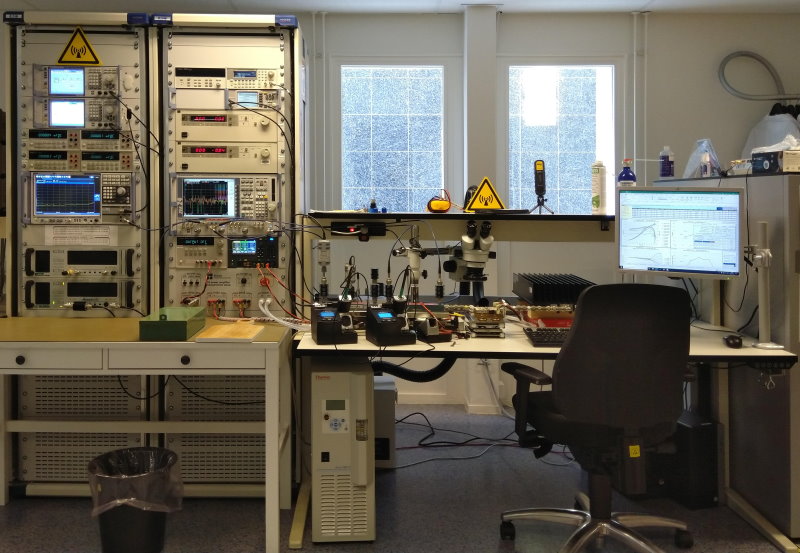
The assembled amplifier is put to the test in a specialized measurement setup in our lab. This fully automated setup can measure all required parameters to characterize the device. Depending on the accuracy of the transistor data and the accuracy of the design in our simulation environment, adjustments can be required. The same Bruco engineer will perform the design, assembly, measurement and tuning of the amplifier, to have an optimal flow and development time. He or she knows all the ins and outs of the design and therefore has the expertise to know which changes have to be made to the amplifier to improve its performance.
When the required performance has been reached, the amplifier is fully characterized. The resulting data is used for the customer documentation. The complete development, from design to characterization, is supported for peak powers up to 1 kW and frequencies up to 4 GHz.
Edited by Nieke Roos


