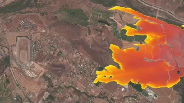
The grid — and the environment in which the grid operates — is changing. This is especially true in California, where an increasing threat of wildfire and intensifying drought cycle have created an environment requiring new approaches to best reduce risk and build resilience.
PG&E has strengthened its electric system with stronger poles, covered power lines and targeted undergrounding.
To combat this growing threat and build a safer, more resilient electric system, Pacific Gas and Electric Co. (PG&E), the state’s largest investor-owned utility, has taken many new safety measures in recent years:
- Conducting enhanced vegetation management
- Developing a robust network of weather stations and cameras
Strengthening the electric system with stronger poles, covered power lines and targeted undergrounding - Installing microgrids and sectionalizing devices that help to minimize risk and reduce the size of public safety power shutoffs
- Developing, testing and deploying new tools and technologies to pinpoint how best to prevent and respond to the risk of wildfires.
Nearly one-third of the electric lines that provide PG&E’s customers with power are now in high fire-threat district (HFTD) areas, as designated by the California Public Utilities Commission (CPUC). The failure of power line apparatus can cause a variety of problems, including fire ignition and other unsafe conditions.
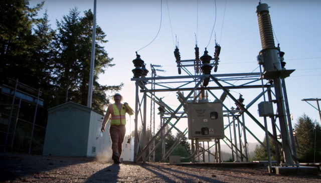
Some types of failures can develop over days or weeks but not be detected by conventional means until final failure occurs. PG&E is combating this by testing and deploying new technologies that can detect developing hazards (and their precursor early-warning signs) long before conventional technologies — thus helping to prevent utility infrastructure-caused wildfires. One of the new technologies is distribution fault anticipation (DFA), which uses substation-based monitors connected to conventional current transformers (CTs) and potential transformers (PTs) to detect incipient failures and other line conditions.
PG&E’s DFA Pilot
Contents
Initially launched in 2019 as a demonstration project through the Electric Program Investment Charge — a statewide program that enables California investor-owned utilities to develop smart grid technology demonstration and deployment projects and evaluate how they support safety, reliability and affordability objectives for the benefit of all electric customers — PG&E installed DFA on seven circuits in three substations. The initial deployment was part of a project to evaluate multiple technologies with potential to provide early warning of developing failures. The circuits are primarily overhead and either three-wire 12 kV or four-wire 21 kV. Based on results from the initial deployment, PG&E is adding DFA to 50 circuits in 2021 and anticipates adding it to another 600 circuits over the next three years. The circuit selection process considers relative wildfire ignition risk.
Utilities have multiple sources for information about their power delivery systems, and optimal outcomes require synergistic use of those sources — but that is a non-trivial process. Some sources are traditional, such as supervisory control and data acquisition (SCADA), while others are newer technologies, such as line sensors that can record waveforms during high-current events and automatically send data to a central server for access by personnel. Several of these new technologies, including DFA, report things that previously were not known to utility personnel, so there is no existing model for how to use them optimally.
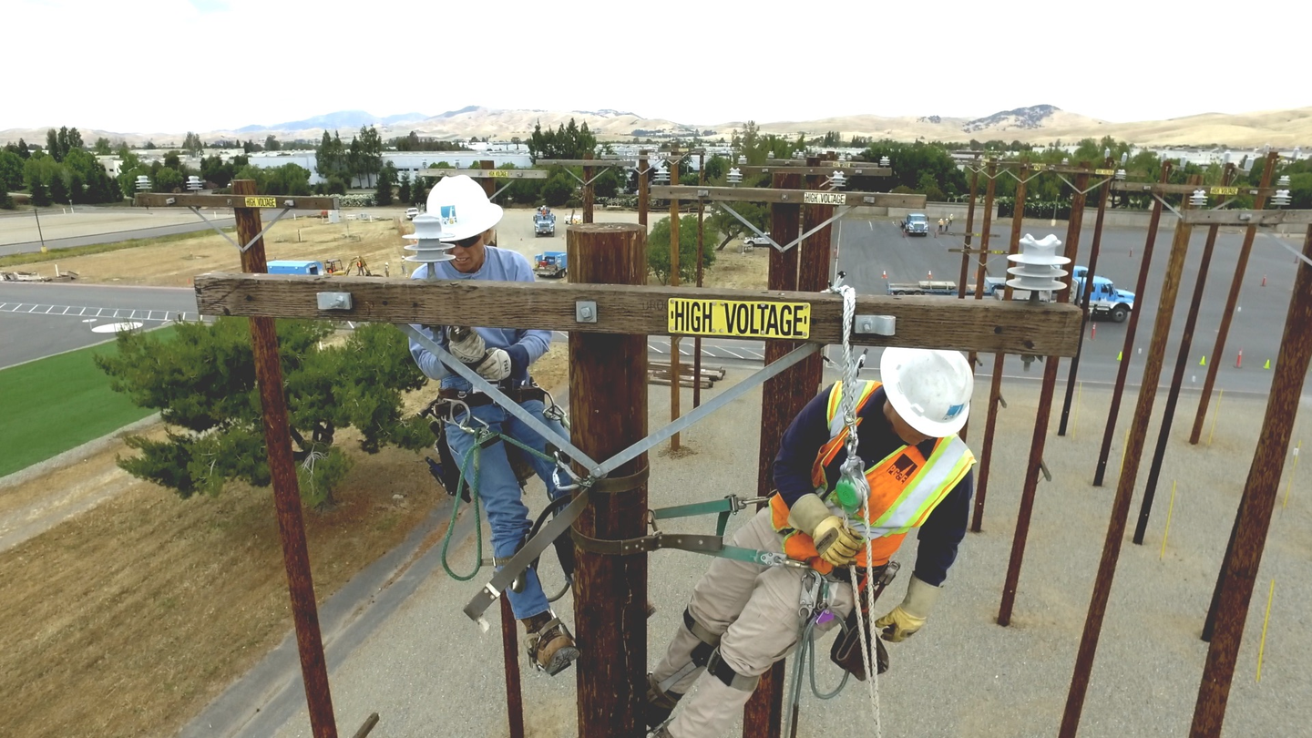 PG&E has strengthened its electric system with stronger poles, covered power lines and targeted undergrounding.
PG&E has installed DFA alongside multiple other technologies with a goal of evaluating not just individual technologies but their best synergistic use, and the first two years of use have confirmed complementary capabilities. Going forward, PG&E will focus efforts on integrating DFA with other new technologies to provide a more complete view of its distribution system.
Texas A&M Engineering developed DFA. PG&E worked with the Texas A&M team throughout the initial pilot period to learn the new technology and assist in the investigation of how DFA can be used with the utility’s other tools to improve overall situational awareness and system health. PG&E will continue engaging with the Texas A&M team while moving forward with its planned expansion and integration efforts.
Pinpointing the Problem
Detection of new types of events, including low-current incipient events, represents new opportunities, but discovering how to act on those new opportunities requires creative thinking and hard work. While the DFA system can detect low-current events that other systems cannot, locating the events can be challenging. Conventional model-based approaches to locating high-current faults work because line impedance is the primary factor influencing fault current magnitude. Such approaches are not useful for locating low-current events, because their current levels are determined primarily by factors other than line impedance, and those factors cannot be ascertained by theoretical deduction.
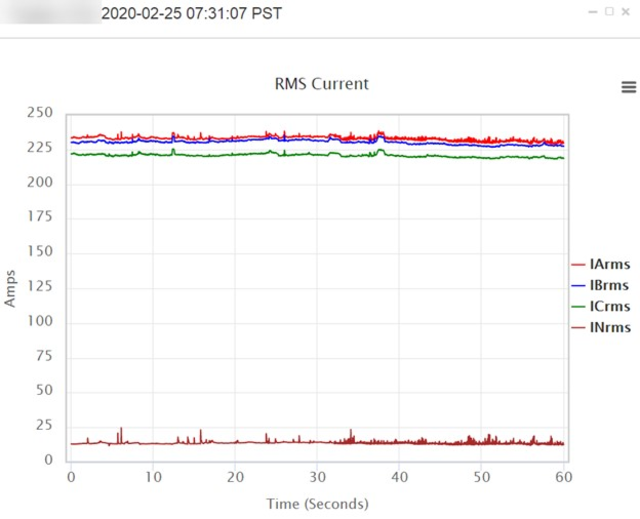
Fortunately, other information sources can, in some cases, provide information to narrow search areas for low-current events like series arcing. For the subject case, the following information proved to have relevance to locating the series arcing:
1. The series arcing was precipitated by a routine overcurrent fault on the circuit. The fault was phase to phase, drew 3104 A and was cleared by fuses in 1.5 cycles. The series arcing began soon thereafter. Relevance: Passage of high current through a current-carrying device can precipitate series arcing in its contacts. If a device begins to exhibit series arcing soon after the occurrence of a high-current fault, then the failing device likely was in the path of the fault current (that is, between the source substation and the location of the high-current fault). Circuit segments not in that path can be excluded from the list of likely locations.
2. The fuses that cleared the high-current fault were replaced two hours later. The series arcing began immediately thereafter. DFA registered both the inrush caused by the fuse replacements and the series arcing thereafter. Relevance: Series arcing only occurs when current is flowing through the failing device. Knowing exactly when the fuses were replaced and that the series arcing started immediately thereafter strongly suggests the failing device is downstream of the fuse location, so other circuit locations can be excluded from the list of likely locations.
3. DFA reported the series arcing was single phase and estimated that 84 kVA of load was being served through the failing device. Relevance: Knowing an approximate amount of connected load beyond the failing device provides additional information to help target searches. The DFA kilovolt-amps estimate is not intended to be highly precise, but rather to differentiate “a lot” from “a little” connected kilovolt-amps capacity being served through the failing device.
4. A small cluster of advanced metering infrastructure (AMI) meters reported anomalies at multiple times coinciding with periods when DFA was reporting series-arcing episodes. Relevance: Series arcing can cause voltage variations to occur at locations served through the failing device. Knowing which meters were registering anomalies and that those meters were on a small part of the section already identified by the first and second pieces of information further targets the search for the failing device.
The fourth piece of information deserves additional discussion. In its experience with other utilities, Texas A&M has documented cases where series arcing caused customer reports of intermittently flickering lights. This is consistent with voltage downstream of the series-arcing device being modulated by the elevated, variable impedance between the device contact surfaces. PG&E determined meters nearest to the series-arcing device, and only those meters, registered multiple voltage anomalies, and that the timing of those anomalies coincided with the active series-arcing periods reported by DFA.
This use of AMI to target such searches is not straightforward though, because of the variability and intermittency of the series-arcing phenomenon. Series arcing tends to manifest repeatedly — in this case, several hundred times — which provides many opportunities for episodes to be registered by the AMI system. Even if only a small percentage of the episodes registers an anomaly with the AMI system, it may be enough to target a search, particularly if the indicating meters are consistent with all other information, in this case, the location of the initial high-current fault and the fuses that interrupted the fault.
Additional discussion is appropriate regarding timelines of low-current incipient failures, such as series arcing. Texas A&M’s experience with DFA at multiple utilities indicates the timeline of the series-arcing process, from initial flare-up until final failure, can vary widely, from less than an hour to several weeks. PG&E has experienced both ends of this time spectrum. The 11-day period in the case study shared here is on the longer end of the spectrum.
Another PG&E example was on the shorter end. It, too, was precipitated by passage of fault current through a failed device, but that case went from initial indication of series arcing to final failure in less than an hour. Therefore, periodic inspections would have low probability of coinciding with the specific interval when a particular series-arcing failure is occurring.
In addition, some series-arcing failures that have been detected by DFA and then located by utilities — prior to an outage, broken conductor or other negative outcome — have had little visible indication of the device’s degraded condition. Routine inspection likely would fail to notice the incipient failure of such devices unless a flare-up were active when a device was being inspected. The point is continuous monitoring provided by DFA (and potentially other technologies) supplements the identification of incipient failures provided by periodic inspections.
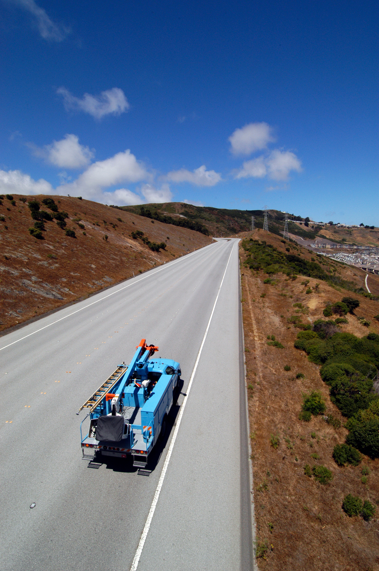 In California, an increasing threat of wildfire and intensifying drought cycle have created an environment requiring new approaches to best reduce risk and build resilience.
The Technology Gap
PG&E’s DFA installations have detected other incipient conditions. Some were high-current events, including a nearby tree that repeatedly caused intermittent momentary faults, a fault-induced conductor slap, and multiple cases of faults that self-cleared without protection operations and, therefore, did not initiate patrols. Others were low-current events, including cases of series arcing and shunt arcing.
DFA has reported dozens of possible shunt-arcing events. It is believed a large percentage of these events, detected on the primary by DFA, represent faults occurring on low-voltage, secondary services. It is possible expanded deployment and systematic field follow-up could provide the basis for more precise characterization of such events and even enhanced classification algorithms. The system design for the DFA platform advantageously enables enhanced algorithms to
be deployed to the existing fleet of DFA monitors, if and when they become available.
Other Use Cases
DFA is a multifunction, data-driven technology. PG&E began its trial of DFA because of the potential to reduce the risk of wildfire ignition. The utility has since found value in other DFA capabilities:
- Capacitor monitoring — PG&E has thousands of switched capacitor banks on its distribution circuits to provide voltage and reactive power support. The utility inspects capacitor banks annually, but some failures could remain undetected between inspections. The DFA system detects routine failures and reports them on a central portal. In addition, DFA detects non-routine capacitor failures, such as arcing internal to capacitor switches and other capacitor hardware. Capacitor arcing causes electrical transients that can precipitate failure of other line apparatus, including other capacitor banks and surge arresters. To PG&E’s knowledge, DFA is the only system that can detect capacitor arcing.
- Ready access to high-quality fault information — Like most utilities, PG&E has modern digital relays at the substation head of its distribution circuits. Depending on make and vintage, those relays may record electrical waveform data when high-current fault events occur, but accessing those records can be difficult, so it is not done on a routine basis. By contrast, the DFA system records high- and low-current events and makes them available in a browser-based portal automatically within minutes of an event.
A Multipronged Approach
Power line failures can ignite fires. No technology or group of technologies can detect all failure phenomena or prevent all ignitions, but new technologies are providing at least partial solutions. Like many other utilities, PG&E has a multipronged approach to reducing fire risks. One key component focuses on the use of new technologies, such as DFA technology, to detect failures and incipient failures.
DFA can detect certain incipient failure mechanisms that other technologies cannot detect, including mechanisms that draw minimal current. Conventional, current-based methods for locating faults do not work for low-current phenomena, but AMI, line sensors and other information sources can aid in finding the location. The fundamental key to addressing these phenomena is knowledge that they are occurring, knowledge that DFA can in many cases provide.
Eric Schoenman, a mechanical engineer working in theutility industry for 25 years, has developed and deployed technologies ranging from small- and large-scale AMI/smart meter platforms, custom cellular network systems and emerging smart grid monitoring systems. Currently, he is an expert operations systems engineer in PG&E’s Distribution Asset Health and Performance Center, where he develops corporate strategy for implementation of distribution grid monitoring technology to reduce wildfire risk. Schoenman has a BSME degree from the University of California, Berkeley.
John Mead, an electrical engineer in the electric power industry for over 35 years, has planned and designed large-scale electric distribution and transmission projects throughout the U.S. He has designed electrical interconnections for over 80 MW of renewable photovoltaic systems and power electronic converters for various energy storage technologies. Currently, he is a principal engineer in the grid technology engineering and evaluation group of PG&E’s Applied Technology Services department, where he evaluates new smart technology in support of the utility’s wildfire mitigation plan. Mead has a BSEE degree and is a registered professional electrical engineer in the state of California.
For More Information:
Texas A&M University | carl.benner@tamu.edu

