The analog revolution
Granted, it’s a slow revolution that relies heavily on designers adopting new design methods. But a handful of companies are moving forward in new areas like analog synthesis and physical layout, and others are improving traditional simulation tools.
“We’re on the cusp of a major change in the way people will do AMS design,” said Rob Rutenbar, a Carnegie Mellon professor of computer engineering and cofounder of a start-up analog EDA company, Neolinear Inc., also in Pittsburgh. “It’s a very cool time to be working on hard-core analog tools. In the 1980s, we were considered lunatics in the wilderness. Fifteen years later, it’s paying off.”
Simulation and layout stages
Simulation is one area where analog designers have been able to rely on EDA tools, most often those based on Spice, the simulation program developed in the early 1970s at the University of California at Berkeley. But these tools are very slow because they simulate at the transistor level. With millions of transistors involved, they are not practical. The reason is that even though most of the transistors in a mixed-signal design are used for the digital component, the entire circuit has to be simulated to make sure that the analog and digital parts work together–an arduous and expensive process.

Market Shares in Mixed-Signal Simulation: Analog and mixed-signal simulators are available from 18 vendors of electronic design automation tools, but the market is dominated by Cadence Design Systems.
Click on the image for the full illustration view.
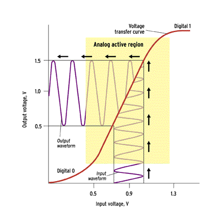
Mixed-signal chips require mixed-signal simulators to verify the behavior of both digital and analog blocks, as well as the interfaces between them. Several analog and mixed-signal simulators are currently on the market, which is dominated by Cadence Design Systems Inc., in San Jose [see pie chart]. So far, though, none of the simulators meets the demands of most analog/mixed-signal designers.
Most likely, mixed-signal simulation will increase the use of mixed-signal HDLs such as Verilog-AMS or VHDL-AMS. Instead of describing each transistor, these languages would describe functions or behaviors that include several transistors. They would give the industry a standard format for simulating the behaviors of groups of transistors rather than of each transistor individually. In the digital world, HDLs were originally used for verifying the behavior of a design through simulation, but they later became the standard input to logic synthesis tools as well.
After a high-level simulation, analog circuits are physically designed with the help of graphics editors. To the user, these editors resemble a drawing program, having the equivalent of shapes and clip art that help the layout designer place and connect the analog transistors. After layout, the analog block is simulated with much more detailed, transistor-level input to the simulation software. Complete analog blocks also need to be simulated within the context of their larger environment, the chip, which presumably includes lots of digital circuitry.
Many users would like today’s transistor-level simulators to be faster and handle bigger designs. “They are comfortable using the tools that they once used to develop 50 000-transistor designs,” said Gary Pratt, a technical marketing manager at Mentor Graphics, in Wilsonville, Ore., “and would simply like that extended to their new multi-million transistor designs. Unfortunately, many are finding that this does not exist, despite vendor claims of high-capacity simulators for mixed-signal designs.” The real capacity of a simulator varies with the design, speed of the machines it runs on, degree of accuracy, and simulation time.
This is why mixed-level simulators are so useful. The designer can trade off the accuracy of simulation at the transistor level against the speed of simulation at the behavioral level by choosing the simulation method appropriate to each block. Simulating the whole chip with selected blocks at different levels of abstraction–a mix of behavioral, cell-level, and transistor-level models–allows the process to run in a reasonable time while verifying the blocks in context of the chip.
But breaking up the system into such levels is no easy task, said Ken Kundert, a specialist in AMS at Cadence Design Systems. In a session at the Electronic Design Processes Workshop held in Monterey, Calif., in April, Kundert argued that a chip architect must settle on a plan that dictates when and how the full chip and its blocks are to be simulated.
EDA vendors say that simulation is one area in which tools are not sufficient if the designers lack a smart simulation strategy. Spokespeople from Mentor, Avant!, and Synopsys agree that mixed-signal and system-on-chip (SoC) designers must develop a top-down design flow to be successful. In a top-down flow, systems are defined at a high level, possibly before any blocks are made. The specifications for the system blocks, developed by chip architects, are handed down to the block designers. In the traditional bottom-up flow, each block is created independently, then stitched together on a chip.
Not all analog designers are faced with AMS. In high-performance analog designs, like those coming from Huibert Verhoeven’s op-amp group at National Semiconductor in Santa Clara, Calif., simulation tools need not handle mixed-signal or mixed-level considerations, but they do need to account for parasitic resistance and capacitance. Verhoeven’s group is doing better with traditional bottom-up analog design flows than with top-down flows and automation because their designs have few transistors and must operate at higher speeds than automation tools can deliver. But Verhoeven said more tools are becoming available for analog components of system-on-chip designs, including automated placement and routing.
